
Process for producing electrodes for solar cells

a technology of solar cells and electrodes, applied in the direction of basic electric elements, electrical apparatus, semiconductor devices, etc., can solve the problems of limited printing resolution, substrate fracture, and inability to proceed, and achieve the effect of simple manner

Inactive Publication Date: 2012-08-21
BASF AG
View PDF19 Cites 6 Cited by
  • Summary
  • Abstract
  • Description
  • Claims
  • Application Information

AI Technical Summary

Benefits of technology

[0008]It is an object of the invention to provide a process for producing electrodes for solar cells, the electrode being configured as a electrically conductive layer, which enables the electrically conductive layer also to be reproduced in very fine structures and which can be performed in a simple manner with the use of large amounts of environmentally hazardous substances.
[0066]Structured application of the dispersion to the carrier is advantageous when particular structures are to be produced in high numbers and the structured application reduces the amount of dispersion which has to be applied to the carrier. This allows less expensive production to be achieved.
[0076]When the electrically conductive particles comprise a material which can oxidize easily, in a preferred process variant, the formation of the metal layer on the structured or fully electrically conductive layer is preceded by at least partial removal of the oxide layer. The oxide layer can be removed, for example, with acids, such as concentrated or dilute sulfuric acid or concentrated or dilute hydrochloric acid, nitric acid, citric acid, phosphoric acid, amidosulfonic acid, formic acid or acetic acid.

Problems solved by technology

One disadvantage of the printing and embossing processes known from the prior art is that printing resolution is limited especially in the case of screenprinting, and conductor tracks with a width of less than 120 μm cannot be printed.
A further disadvantage of the printing and embossing processes is that they do not proceed contactlessly and the substrate can fracture owing to the pressure applied by the contact, for example with screen and blade in the course of screenprinting.
The contactless processes known from the prior art are generally etching processes, which have the disadvantage that acids and alkalis have to be used for the etching and subsequent removal of the covering resist.
In addition, several complicated process steps are required.

Method used


Image

  • Process for producing electrodes for solar cells
  • Process for producing electrodes for solar cells

Examples


Embodiment Construction

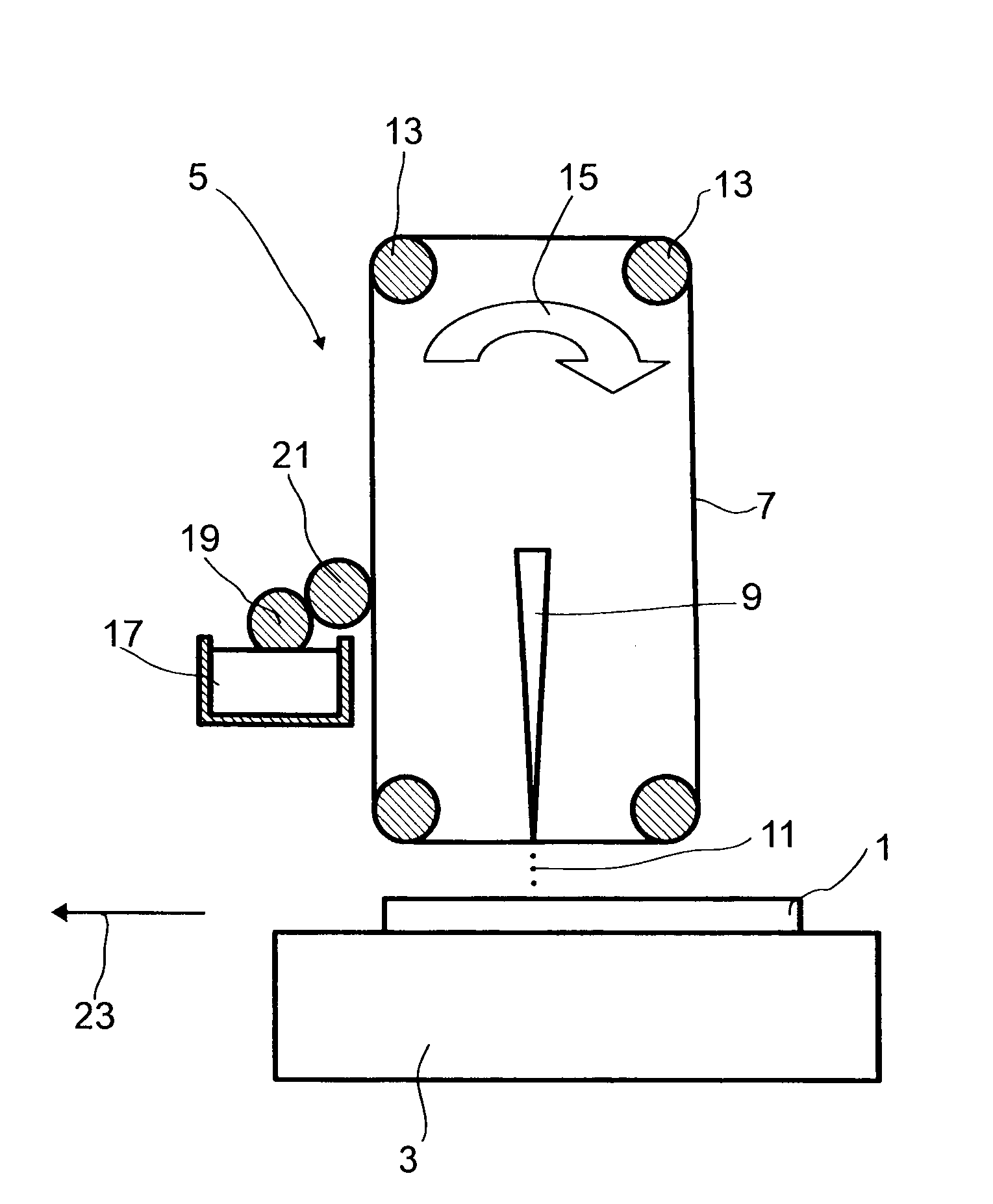
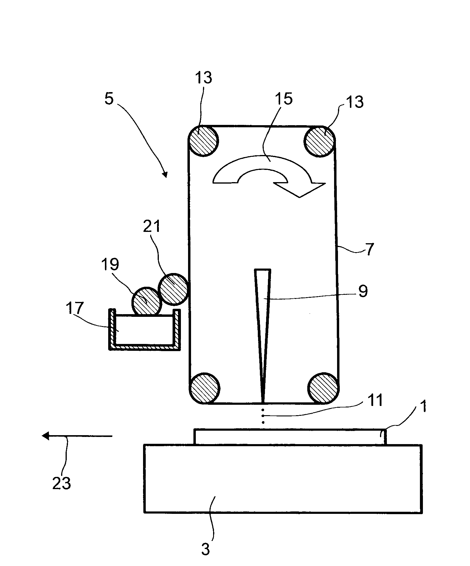
[0084]To produce electrodes for solar cells, a substrate 1 is supplied to a coating device 5 with a transport device 3 which is shown here only schematically. Suitable transport devices 3 are any desired transport devices known to those skilled in the art. For example, the transport device 3 may comprise a belt on which the substrate 1 is positioned and which is conducted around rollers in order to move the substrate 1. Alternatively, for example, it is possible to use feeders with which the substrate 1 is positioned in the coating device 5. It is also possible to use any other suitable transport device known to those skilled in the art.

[0085]The coating device 5 comprises a carrier 7 which is coated with a dispersion. In order to coat the substrate 1, the carrier 7 coated with the dispersion is irradiated with a laser 9. This detaches the dispersion from the carrier 7 and transfers it to the substrate 1. This is done, for example, by evaporating a small amount of the solvent which ...


PUM


Abstract

The invention relates to a process for producing electrodes for solar cells, the electrode being configured as an electrically conductive layer on a substrate for solar cells, in which, in a first step, a dispersion comprising electrically conductive particles is transferred from a carrier to the substrate by irradiating the dispersion with a laser and, in a second step, the dispersion transferred to the substrate is dried and / or hardened to form the electrically conductive layer.

Description

BACKGROUND OF THE INVENTION[0001]The invention relates to a process for producing electrodes for solar cells, the electrode being configured as an electrically conductive layer on a substrate for solar cells.[0002]Solar cells comprise generally a semiconductor substrate with a number of p- and n-doped regions which generate a potential difference and a voltage with one another when they are exposed to sunlight. In order to be able to draw off the voltage, electrodes are applied to the surfaces of the semiconductor substrate. At present, the electrodes are generally applied in a screenprinting process. The production of electrodes in a screenprinting process is described, for example, in EP-A 1 911 584, US-A 2007 / 0187652 or U.S. Pat. No. 4,375,007.[0003]As an alternative, for example, WO 2008 / 021782 discloses first applying a metal layer to the semiconductor material, applying a covering resist by an inkjet printing process, which covers the regions which are to form the structure of...

Claims


Application Information

Patent Timeline
IPC IPC(8): H01L21/44
CPCH01L31/022425Y02E10/50H01L31/18H01L31/04H01L31/0224
Inventor LOCHTMAN, RENEWAGNER, NORBERTKACZUN, JURGENPFISTER, JURGEN
Owner BASF AG
Learn More