Fiber-optic thermometer

Active Publication Date: 2017-05-11
UNIV LAVAL
View PDF10 Cites 2 Cited by
  • Summary
  • Abstract
  • Description
  • Claims
  • Application Information

AI Technical Summary

Benefits of technology

The invention is a thermometer made from fiber optics that is simpler and less expensive to produce and dispose of. Its technical effects are improved accuracy and ease of use.

Problems solved by technology

Existing (traditional) thermometers presents a number of disadvantages that limit the scope of their use.
For example they often lack mechanical flexibility or they may contain metal or semiconductor elements which are sensitive to electromagnetic fields (EMF) making it difficult or impossible to use them in applications where such fields are present.
However, existing fiber optic thermometers are largely based on multi-mode fibers (gallium arsenide, etc.), which are sensitive to bending (modal composition) and therefore limit their utilisation in situations where the fiber must be inserted in material or anatomical structures with irregular shapes.
Furthermore, existing single-mode fiber thermometers which rely Brillouin Sensors (US patent application 20040208413, Fiber Bragg Gratings (U.S. Pat. No. 6,072,922), precise reflective path length (U.S. Pat. No. 8,195,013) and the like are complex, and therefore costly to make.
Existing fiber optic sensors relying on changes in attenuation of the evanescent field (see U.S. Pat. No. 5,058,420 that describes a liquid level sensor, U.S. Pat. No. 4,203,326) have been developed but optical fiber thermometers typically measure a spectral change with temperature that requires complex reading equipment.

Method used


Image

  • Fiber-optic thermometer
  • Fiber-optic thermometer
  • Fiber-optic thermometer

Examples


Embodiment Construction

[0029]The invention provides a fiber optic thermometer the functioning of which is based on the variation of the power of the light propagated within the fiber in response to changes in the refractive index of a temperature-dependent refractive index material. The fiber optic thermometer of the invention is simpler and cheaper to make than existing fiber optic thermometers and provides good temperature and spatial resolution.

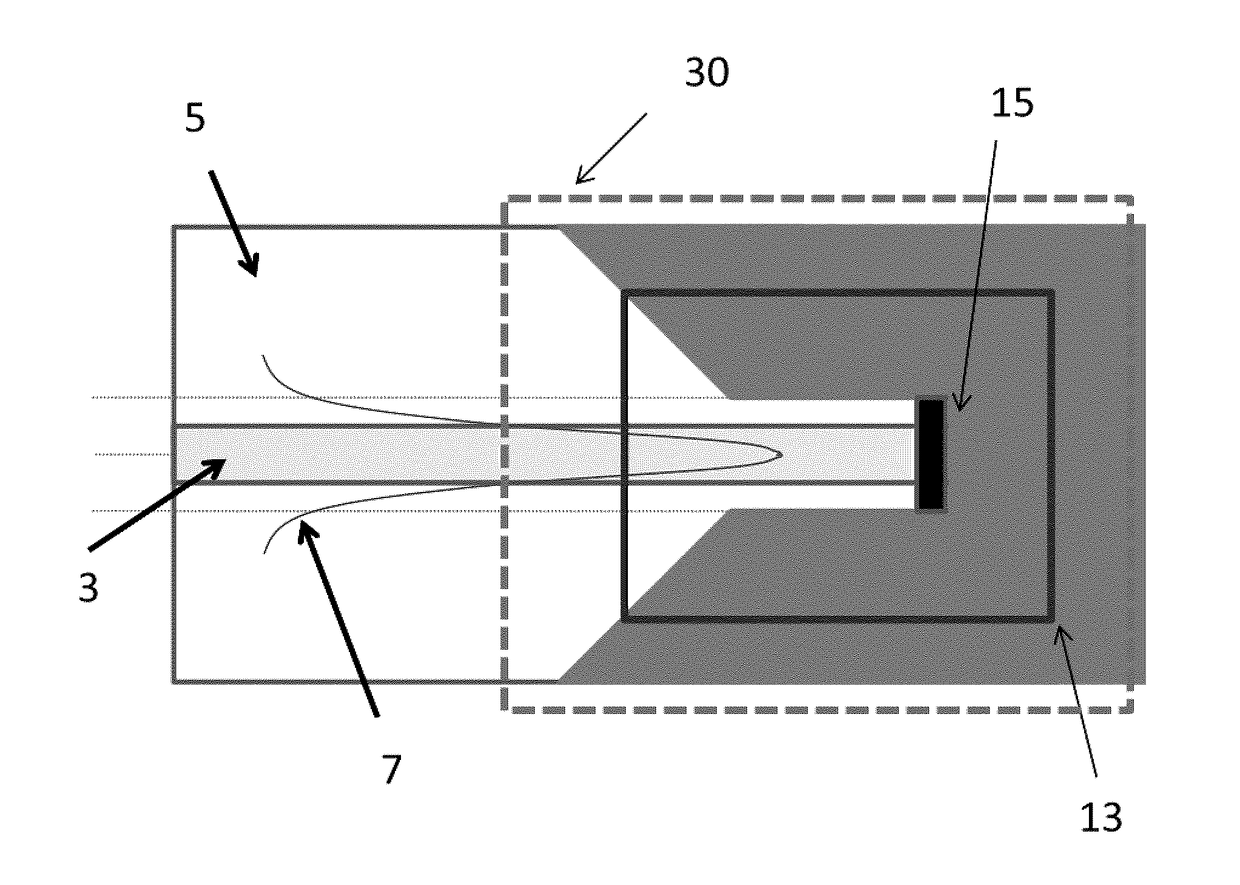
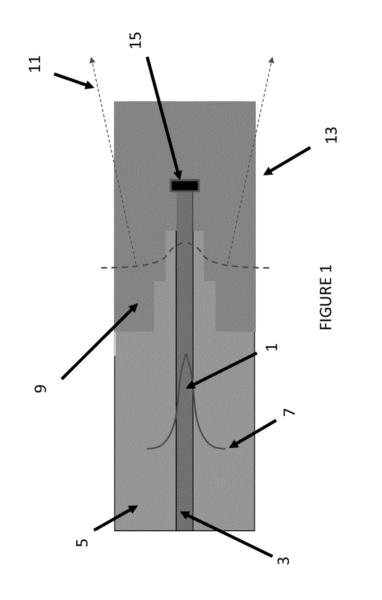
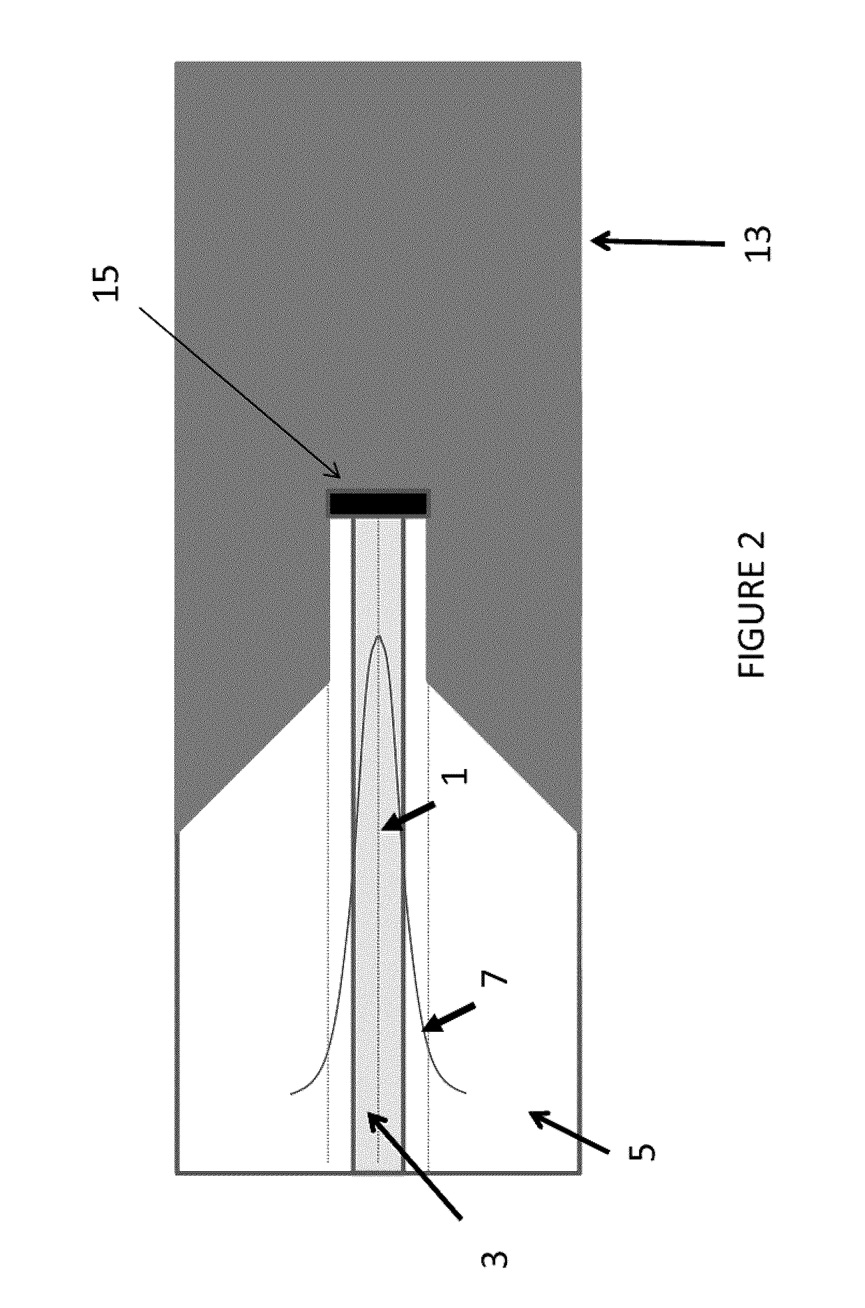
[0030]The thermometer comprises an optic fiber based probe that is coupled to a light source and a photo detector. FIG. 1 provides a highly schematic diagram of an example of the fiber optic probe of the invention illustrating the working principle of the device. Light 1 is propagated within the core 3 of the fiber according to a certain mode or plurality of modes and the difference in the refractive index between the core and the cladding 5 (having a lower refractive index) provides an interface that reflects the light therefore allowing light propagation by to...


PUM


Abstract

A fiber-optic thermometer probe has an optical fiber with a sensing portion, namely a region of reduced cladding thickness coated with a temperature-dependent refractive index material to provide variations in propagated light power upon changes in temperature in a vicinity of the sensing portion. A reflective interface optically coupled to a core of the optical fiber reflects light propagated therein. The sensing portion can be the tip and prepared by etching using a dipping process.

Description

[0001]The present application claims priority of U.S. patent application Ser. No. 61 / 832,854 filed Jun. 8, 2013.TECHNICAL FIELD[0002]The present invention generally relates to processes and devices using fiber-optic sensors and more particularly to fiber-optic temperature probes.BACKGROUND OF THE INVENTION[0003]Existing (traditional) thermometers presents a number of disadvantages that limit the scope of their use. For example they often lack mechanical flexibility or they may contain metal or semiconductor elements which are sensitive to electromagnetic fields (EMF) making it difficult or impossible to use them in applications where such fields are present.[0004]Fiber optic technologies have been developed to allow detection of environmental parameters such as temperature. However, existing fiber optic thermometers are largely based on multi-mode fibers (gallium arsenide, etc.), which are sensitive to bending (modal composition) and therefore limit their utilisation in situations w...

Claims


Application Information

Patent Timeline
IPC IPC(8): G01K11/32
CPCG01K11/3206G01K11/00
Inventor GALSTIAN, TIGRAN
Owner UNIV LAVAL
Why Eureka
Try Eureka