Mounting

a technology of mounting and supporting, applied in the direction of shock absorbers, machine supports, transportation items, etc., can solve the problems of high acceleration on the supported, character stiffness, and mounting will “bottom out”, and achieve the effect of reducing high frequency acceleration

a technology of mounting and supporting, applied in the direction of shock absorbers, machine supports, transportation items, etc., can solve the problems of high acceleration on the supported, character stiffness, and mounting will “bottom out”, and achieve the effect of reducing high frequency acceleration

US20180216687A1Active Publication Date: 2018-08-02PUMPKIN MOUNTS LLC

Image

  • Mounting
  • Mounting
  • Mounting

Examples


Embodiment Construction

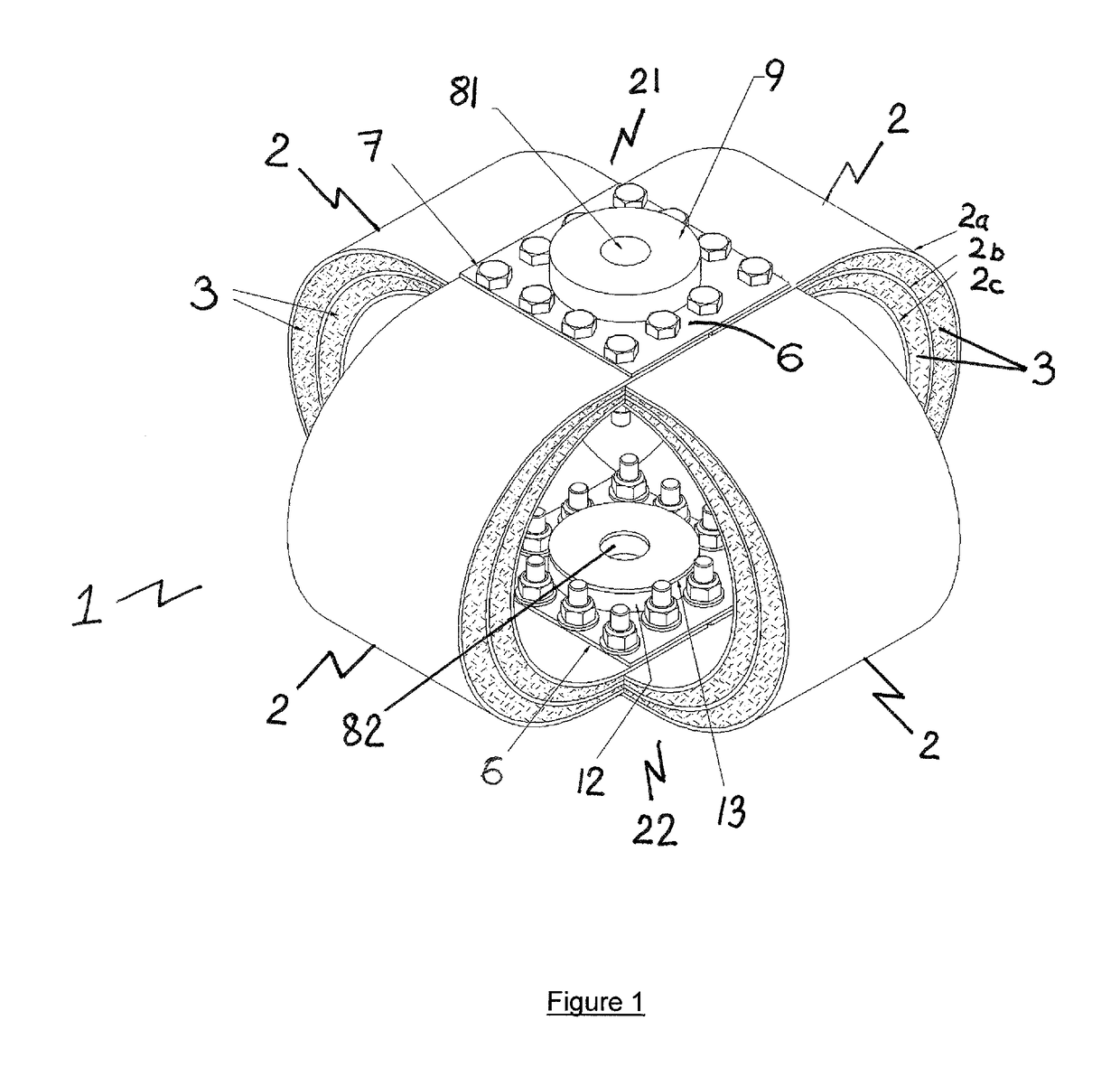
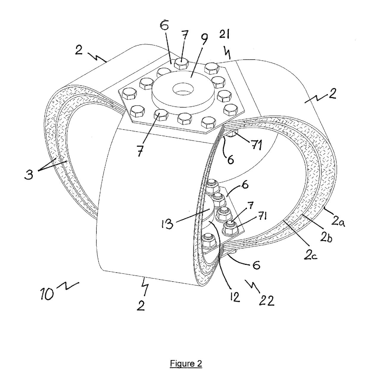
[0055]Referring to FIG. 1 there is shown an exemplary mount 1 comprising four substantially U-shaped leaf spring members 2. Referring to FIGS. 2 and 3, there is shown an exemplary mount 10 comprising three substantially U-shaped leaf spring members 2.

[0056]Each leaf spring member 2 is formed from at least two leafs. In FIGS. 1, 2 and 3, each leaf spring member is shown having three leafs 2a, 2b, 2c. Preferably, each leaf 2a, 2b, 2c is formed from a band of stainless steel, however any suitable material may be used. Between respective adjacent leafs 2a, 2b, 2c there is defined a space 3 which is filled with a viscoelastic damping compound. Alternatively, space 3 may be filled with a wire mesh damping material.

[0057]With reference to FIG. 3, each leaf spring member 2 has an upper 21 and lower 22 end in use. The upper and lower ends represent respective terminal ends of each leaf spring member 2. As shown in FIGS. 1 and 2, the respective adjacent leaf spring members 2 of a mount 1, 10 ...


PUM

PropertyMeasurementUnit
angleaaaaaaaaaa
massaaaaaaaaaa
shore hardnessaaaaaaaaaa

Abstract

An improved shock isolating mounting comprising at least three substantially U-shaped leaf spring members, each leaf spring member comprising at least two leafs arranged to define a space therebetween. In one arrangement, the respective at least three substantially U-shaped leaf spring members are arranged in an array having a substantially equal angular spacing between adjacent spring members.

Description

FIELD OF THE INVENTION[0001]The present invention relates to an improved mounting adapted to isolate shocks and to reduce the acceleration of items supported by such a mounting.BACKGROUND TO THE INVENTION[0002]Many industrial applications require the use of shock and vibration isolators to protect installations, machinery and equipment from hostile environments. One of the most challenging environments is on naval ships where it is customary for systems, machinery and equipment to be required to withstand a specific shock and vibration environment imposed by underwater explosive attack and the rigours of naval service. To provide protection of critical or vulnerable systems it is customary to use shock mounts or isolators to perform the function of reducing the acceleration imparted to the mounted item while also controlling displacement within acceptable levels. It is also a requirement to assure the captivity of the mounted item to a specified shock input to prevent it breaking lo...

Claims


Application Information

Patent Timeline
02 Aug 2018
Publication
US20180216687A1
IPC
F16F3/02; F16F1/30; F16F1/18; F16F15/08; F16M5/00; F16F1/20; F16F3/12; F16M7/00; B65D90/14
CPC
F16F3/023; F16F1/30; F16F1/187; F16F15/085; F16M5/00; F16F1/20; F16F3/02; F16F3/12
Inventors
THOMPSON, PHILLIP R.; MISSELBROOK, NICOLAS K.