
LED lighting device, and method of extracting light using LED lighting device

a technology of led lighting and led lighting, which is applied in the direction of semiconductor devices for light sources, lighting and heating apparatus, light source combinations, etc., can solve the problems of difficult efficient diffuse and reflect light, increase in the number of components, and complex configuration, and achieve uniformly irradiating different regions, simplifying structure and compact

Active Publication Date: 2018-08-02
FURUKAWA ELECTRIC CO LTD +1
View PDF6 Cites 3 Cited by
  • Summary
  • Abstract
  • Description
  • Claims
  • Application Information

AI Technical Summary

Benefits of technology

The present invention aims to simplify the configuration and make an LED lighting device that is compact and can irradiate different regions uniformly. The patent also provides a method for extracting light using the LED lighting device.

Problems solved by technology

WO2010-001604 is formed by laminating a PET film or white ink having light reflectivity on a metal or resin member, and therefore it is difficult to efficiently diffuse and reflect light.
According to Japanese Patent Application Laid-Open Publication No. 2013-545662, as the reflector plate is separately provided from a supporting structure such as a board or the like to which the LED light source is attached, and therefore the number of components increases and a configuration becomes complex.
The methods disclosed in Japanese Patent Application Laid-Open Publication No. 2009-67098 and Japanese Patent Application Laid-Open Publication No. 2013-502042 merely multiply reflect light from the LED light source by the diffusion sheet or the reflector plate and are not necessarily efficient.
In addition, as the lighting device is arranged inside an illumination space and thus a board of the lighting device adversely absorbs return light of the illumination light, which is emitted from the light source and then reflected by a reflecting surface, the use efficiency of the light is lowered.
Also, as the LED board absorbs the light and is heated, it is concerned to shorten the operating life of the light source.
Also, when used as an automotive interior illumination, it is in particular undesirable because the heat of the LED light source is radiated in an interior of the vehicle through the switch.
As a molded component of a highly reflective resin material such as a highly reflective polycarbonate or the like is used for a frame, the lighting device becomes heavy.
Hei 11-185517, as the LED light sources are arranged in a staggered layout, it requires a number of LED light sources, and therefore the number of components increases and a configuration becomes complex.

Method used


Image

  • LED lighting device, and method of extracting light using LED lighting device
  • LED lighting device, and method of extracting light using LED lighting device
  • LED lighting device, and method of extracting light using LED lighting device

Examples


first embodiment

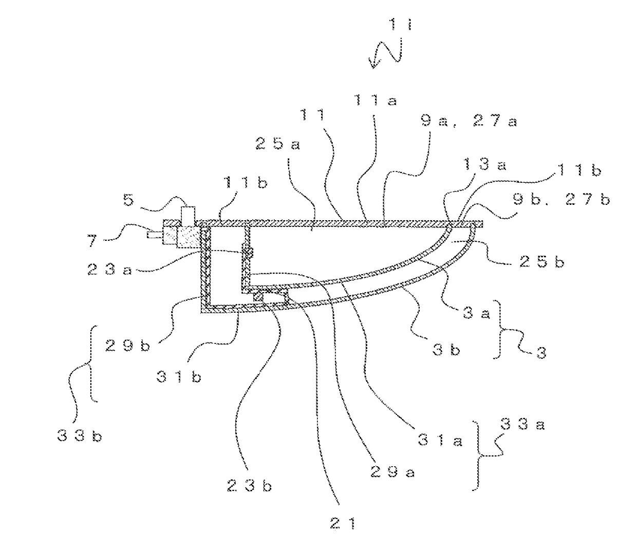
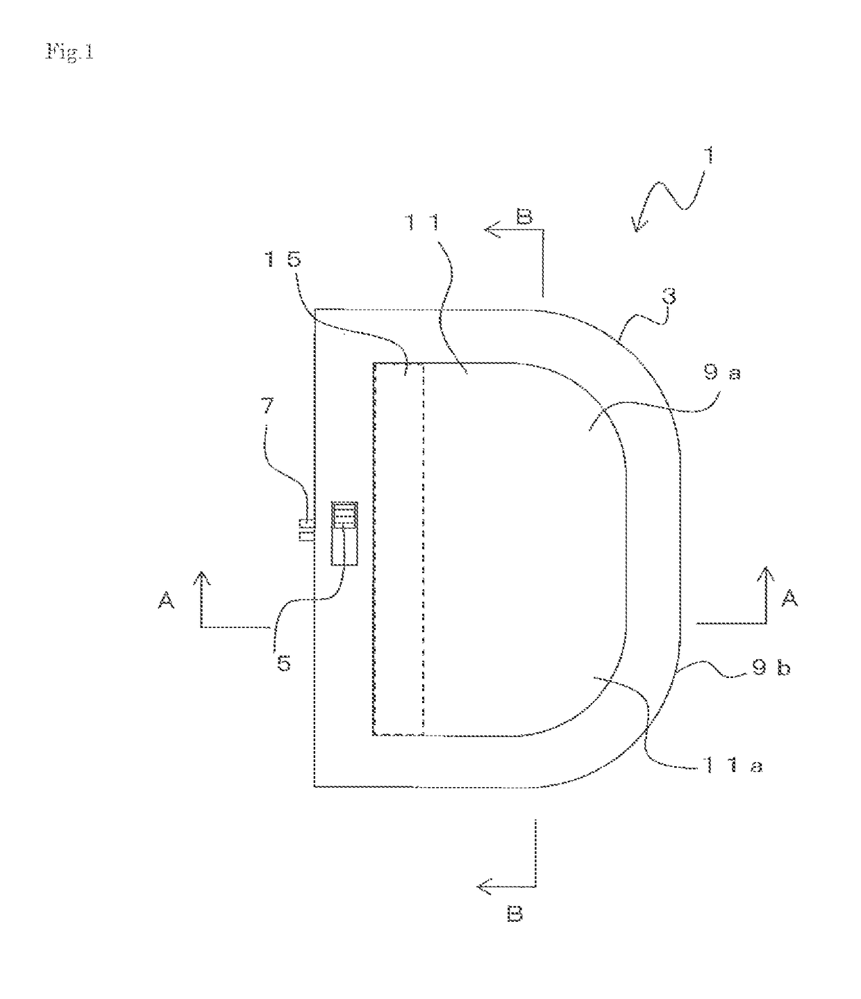
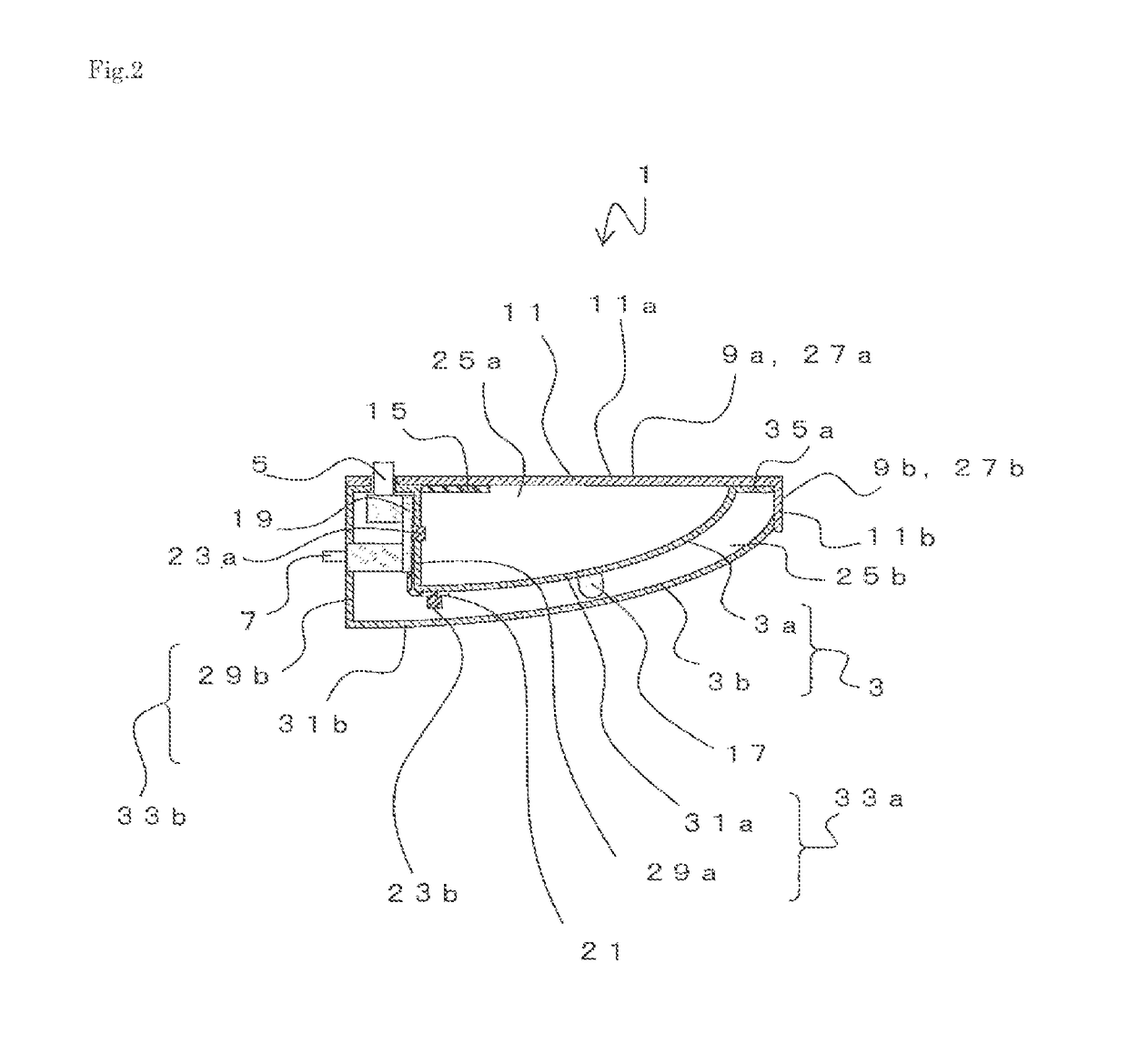
[0119]Hereinafter, embodiments of the present invention will be described with reference to the accompanying drawings. FIG. 1 is a plan view showing an LED lighting device 1. FIGS. 2 and 3 are cross-sectional views of the LED lighting device 1. FIG. 2 is a cross-sectional view of the LED lighting device 1 taken along the line A-A in FIG. 1. FIG. 3 is a cross-sectional view of the LED lighting device 1 taken along the line B-B in FIG. 1.

[0120]The LED lighting device 1 includes, as its major components, a frame 3, a light transmissive member 11, LED light sources 23a and 23b, and a selector switch 5 or the like.

[0121]The frame 3 has an outer frame 3b made from microcellular foam resin, and an inner frame 3a made from the microcellular foam resin in which two recess portions are provided to be spaced apart from each other. The two recess portions of the inner frame 3a are arranged together inside the outer frame 3b. In other words, the frame 3 has a dual structure. It should be noted t...

second embodiment

[0203]Hereinafter, a second embodiment will be described. FIG. 5 is a cross-sectional view showing an LED lighting device 1a according to the second embodiment. FIG. 6 is a cross-sectional view taken along the line C-C in FIG. 5, and FIG. 7 is a cross-sectional view taken along the line D-D in FIG. 5. It should be noted that, in the following description, components having the same function as those in the LED lighting device 1 are denoted with the same reference signs in FIGS. 1 to 4 and duplicable description will be omitted.

[0204]The LED lighting device 1a differs from the LED lighting device 1 in that the LED lighting device 1a is provided with one recess portion 33a of the inner frame 3a instead of two recess portions and one LED light source 23a is arranged at the inner frame 3a. Other configurations are similar to those in the LED lighting device 1. The opening 27a of the inner frame 3a is formed substantially on the same plane.

[0205]According to the second embodiment, the si...

third embodiment

[0206]Hereinafter, a third embodiment will be described. FIG. 8 is a cross-sectional view showing an LED lighting device 1b according to the third embodiment, and FIG. 8 corresponds to FIG. 2.

[0207]The LED lighting device 1b differs from the LED lighting device 1 in that all components are mounted onto the circuit board 19 only without the flexible flat cable 21 being used. The circuit board 19 is disposed on an outer face of the wall portion 29a of the inner frame 3a. Furthermore, the circuit board 19 protrudes in an extending direction of the wall portion 29a toward the direction of the curved face portion 31b of the outer frame 3b.

[0208]The LED light sources 23a and 23b are arranged to be spaced apart from each other on the same plane direction of the circuit board 19. A pair of LED light sources 23a is exposed to the respective light guide spaces 25a through holes formed in the respective wall portions 29a of the inner frame 3a. Also, the LED light source 23b emits light in the...


PUM


Abstract

A frame has an outer frame made of microcellular foam resin, and two inner frames made of the microcellular foam resin. The two inner frames are arranged together inside the outer frame. Both of the inner frames and the outer frame include openings provided at respective upper portions and recess portions formed downwardly from the openings, respectively. An LED light source, which is arranged inside a light guide space, emits light with a light emitting face thereof directing toward the light guide space. Accordingly, light from the LED light source is uniformly emitted from a light extraction portion. Also, an LED light source arranged inside a light guide space emits light directing toward the light guide space. Accordingly, light from the LED light source is uniformly emitted from a light extraction portion.

Description

TECHNICAL FIELD[0001]The present invention relates to an LED lighting device that is compact and capable of uniformly irradiating different regions, respectively, and relates to method of extracting light using the LED lighting device.BACKGROUND[0002]An LED (Light Emitting Diode) lighting has become widely used because the LED lighting is energy saving and has a longer operating life, and a number of lighting devices using the LED have been so far proposed. One of those lighting devices is a device in which a light reflector plate is arranged inside a frame of the lighting device and light is diffused and reflected to emit in order to improve an illuminance of the lighting device and to diffuse light.[0003]For example, a certain reflector plate has been proposed that is inclined such that the reflector plate gets closer toward a light extraction portion as going farther from a light source (International Publication of PCT International Application No. WO2010-001604).[0004]Also, a c...

Claims


Application Information

Patent Timeline
IPC IPC(8): F21V7/04F21V23/00F21V3/00F21V9/08F21V25/12B60Q3/60
CPCF21V7/04F21V23/004F21V3/00F21V9/08F21V25/12B60Q3/60F21Y2115/10F21Y2113/13F21V15/01F21V23/04G02B5/02G02B5/10F21V7/0016F21V7/0025B60Q3/74F21S43/40F21S43/30F21S43/31F21S43/315F21S43/243
Inventor INOUE, SYOUTAKUBOTA, TETSUJIYAMAMOTO, SYUNJIKOAIZAWA, HISASHIKAISE, TOMIO
Owner FURUKAWA ELECTRIC CO LTD
Learn More