Temporarily Impairing Vision of Selected Occupants of an Area

Active Publication Date: 2018-08-02
LIGHTGUARD LTD
View PDF0 Cites 4 Cited by
  • Summary
  • Abstract
  • Description
  • Claims
  • Application Information

AI Technical Summary

Benefits of technology

The invention is a system for temporarily disabling selected occupants of an area using flashing units and eye protection units. The flashing units generate flashes of light that are strong enough to temporarily disable people who see them. The eye protection units block light when a control signal is asserted, and they transmit light when the control signal is not asserted. The system is synchronized in time so that all the flashing units and eye protection units work together as one synchronized system. The system uses a predetermined time sequence to activate the flashing units, and the first controller stores data that specifies this sequence. The system can be controlled using a wired connection, an RF signal, or an optical signal to synchronize the first controller and the second controller. The flashing unit includes a substrate, LEDs, a heat sink, a driver circuit, and a first controller. The heat sink absorbs the heat generated by the LEDs, and the driver circuit drives the LEDs to generate a flash of light in response to the first control signal. The first controller stores data that specifies the predetermined time sequence for activating the LEDs, and the first controller asserts the first control signal at appropriate times to cause the driver circuit to drive the LEDs at the specified times. The system can be controlled using a wired connection, an RF signal, or an optical signal to synchronize the first controller and the second controller. The eye protection unit includes a shutter that blocks light when the control signal is not asserted, and the shutter is designed to open and close at specific times to transmit light during the flash. The system can be used in various areas to temporarily disable people who may need to be temporarily disabled for safety or other purposes.

Problems solved by technology

These operations can be extremely dangerous, as the terrorists can be expected to open fire as soon as they see someone entering the area that they control.
But this approach has a number of drawbacks.
Second, if the transmission of the trigger pulse from the control unit to the viewer subsystems is disturbed (e.g. due to interference or jamming) or fails to reach the viewer subsystem, the shutters will not close at the proper time, and the law enforcement personnel using the system could also be disabled by the flashes.

Method used


Image

  • Temporarily Impairing Vision of Selected Occupants of an Area
  • Temporarily Impairing Vision of Selected Occupants of an Area
  • Temporarily Impairing Vision of Selected Occupants of an Area

Examples


Embodiment Construction

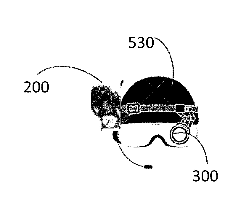
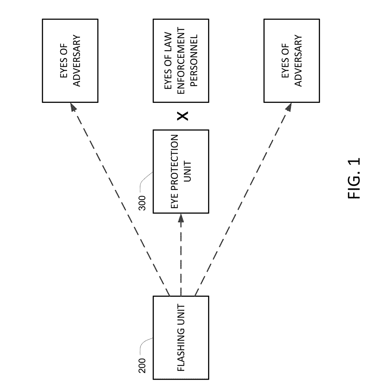
[0033]FIG. 1 is a block diagram of a secure system for temporary blinding adversaries using powerful light flashes without hampering the effectiveness of the law enforcement personnel (LEP) that are sent to neutralize the adversaries. The system includes one or more light flashing units (FU) 200 and one or more eye protection units (SE) 300. These eye protection units may be implemented as switchable eyeglasses, switchable goggles, or other switchable optic units. The FU 200 and the SE 300 are synchronized so that the SE prevents the flashes of light from reaching the eyes of the LEP.

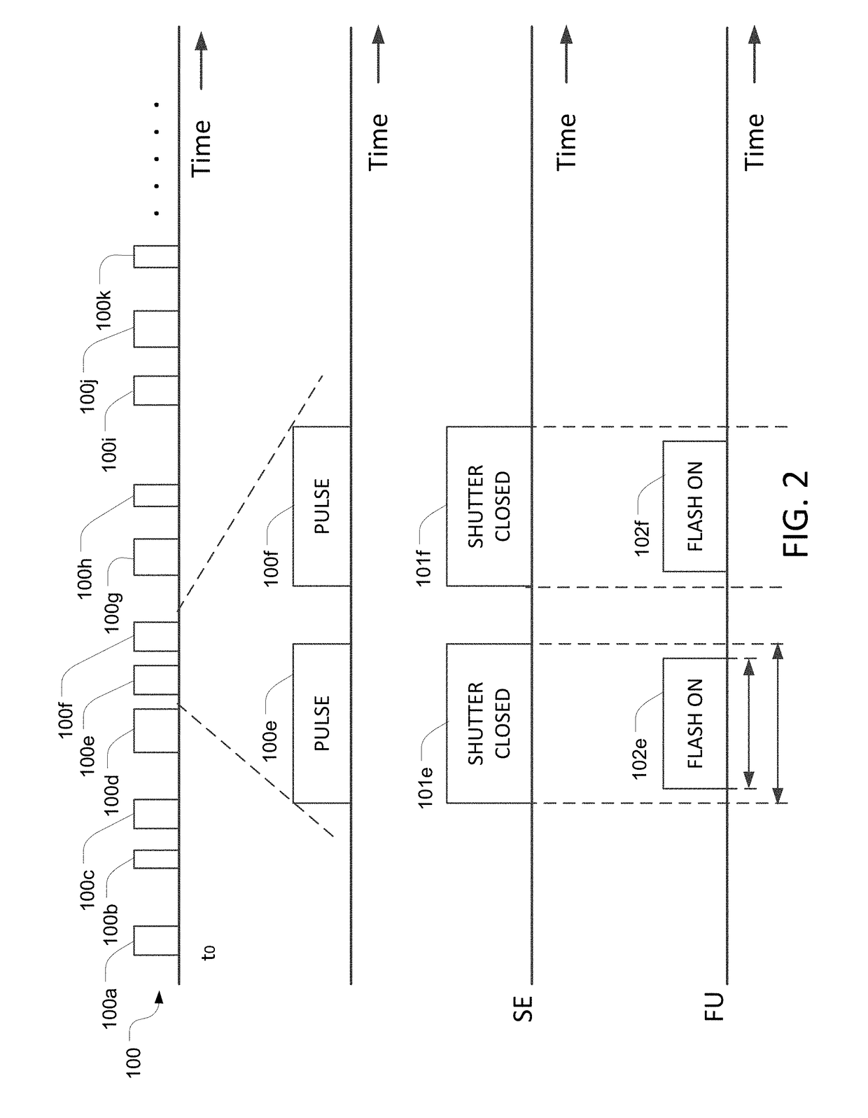
[0034]The LEP wear the SE 300 when entering the relevant area. The SE 300 have shutters that open and close in response to an internal control signal. When the shutters are open, the LEP can see through the SE normally. But when the shutters are closed, practically no light can reach the eyes of the LEP (or the sensors of alternative electro-optic (EO) devices used by LEP, such as night goggles, cameras...


PUM


Abstract

A system for temporarily disabling selected occupants of an area includes one or more flashing units and one or more eye protection units. Each flashing unit includes a light source that generates flashes of light sufficiently bright to temporarily disable people who see the flashes. Each eye protection unit includes a shutter that blocks light while the flashes are being generated. Each flashing unit and each eye protection unit stores data that specifies when the flashes will occur, and are synchronized with each other to ensure that the shutters are closed during each flash. A controller in each flashing unit and a controller in each eye protection unit is configured to change, at coordinated times, the data that specifies when the flashes will occur. In some embodiments, the light source comprises LEDs and the flashing units have heat sinks configured to absorb heat generated by the LEDs.

Description

CROSS REFERENCE TO RELATED APPLICATIONS[0001]This Application claims the benefit of U.S. Provisional Application 62 / 452,642, filed Jan. 31, 2017, which is incorporated herein by reference in its entirety.BACKGROUND[0002]In certain situations, it may be necessary to enter an area that is held by terrorists or other adversaries to overcome them and, if necessary, to free any hostages they may be holding. The area could be a house, room, the inside of an airplane, etc. It could also involve secured areas, bank robberies, violent demonstrators, etc. These operations can be extremely dangerous, as the terrorists can be expected to open fire as soon as they see someone entering the area that they control.[0003]U.S. Pat. No. 7,220,957 describes a prior art approach for disabling adversaries using pulses of light. The '957 patent uses a control unit that transmits trigger pulses to both a lighting subsystem and a viewer subsystem. The lighting subsystem generates a flash of light every time...

Claims


Application Information

Patent Timeline
IPC IPC(8): F41H13/00H05B37/02F21V11/00F21V29/70
CPCF41H13/0087H05B37/0281F21V11/00F21V29/70F21Y2115/10F21S9/02F41A17/08H05B47/16Y02B20/40
Inventor PALTI, YORAM
Owner LIGHTGUARD LTD
Why Eureka
Try Eureka