
Light source module

Active Publication Date: 2018-08-09
GUANGDONG JETFAST PORTABLE LIGHTING
View PDF8 Cites 0 Cited by
  • Summary
  • Abstract
  • Description
  • Claims
  • Application Information

AI Technical Summary

Benefits of technology

The technical effects of this patent include: easier and more convenient assembly, no bad connection or short circuit, reduced inner resistance and power consumption, more flexible and convenient material and performance choices for reflector lamp cup, decreased manufacture cost, and increased usefulness.

Problems solved by technology

However, the foregoing flashlight can achieve the illuminating function by providing the necessary electric energy to the light source module, but the following disadvantages are discovered in actual use.
1. In the foregoing flashlight structure, the reflector lamp cup of the lampshade base is conducted to the negative electrode of the light source module to do power transmission, so it is appeared that the assembly is very inconvenient, and the bad connection or short circuit is occurred more easily, resulting that the light source module cannot illuminate; furthermore, it is consumed more electric energy due to the larger inner resistance of the reflector lamp cup.
2. In the foregoing flashlight structure, the reflector lamp cup of the lampshade base is conducted to the negative electrode of the light source module to do power transmission, so the reflector lamp cup needs to be made of metal material, not only making limit for the material choice and the performance of the reflector lamp cup, but also the manufacture cost is increased.

Method used


Image

  • Light source module
  • Light source module
  • Light source module

Examples


Embodiment Construction

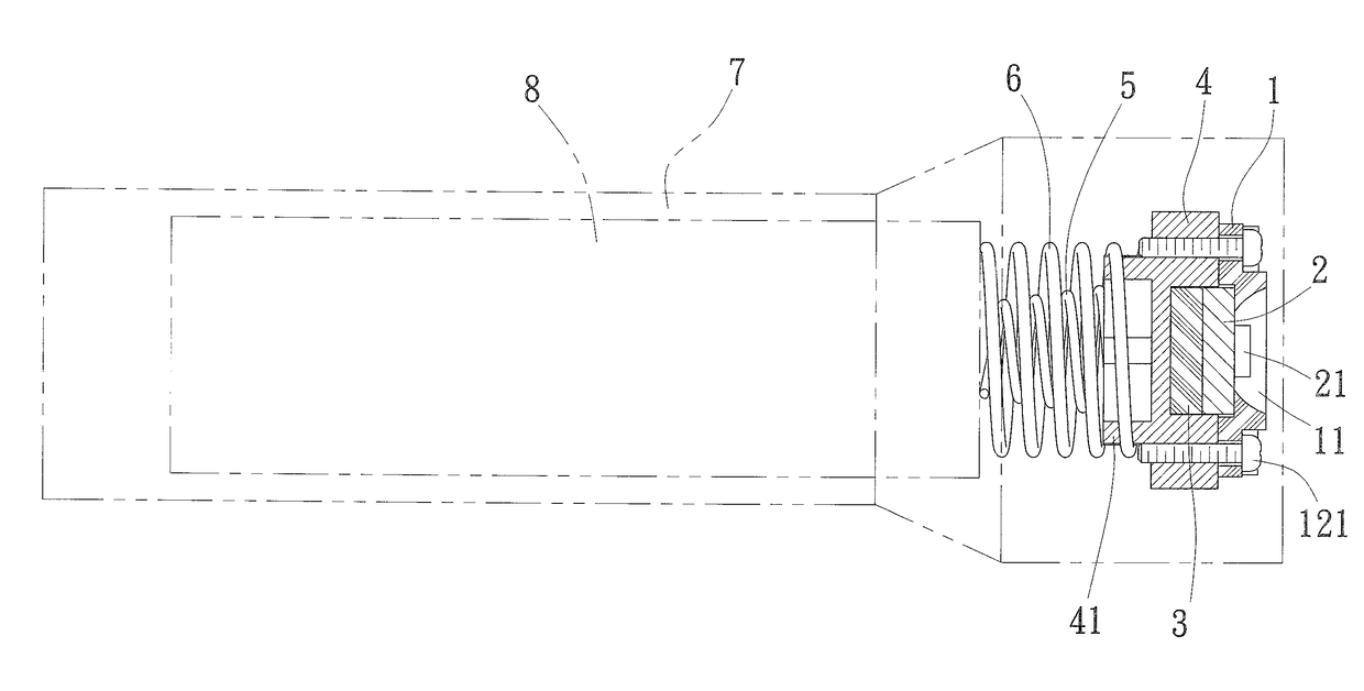
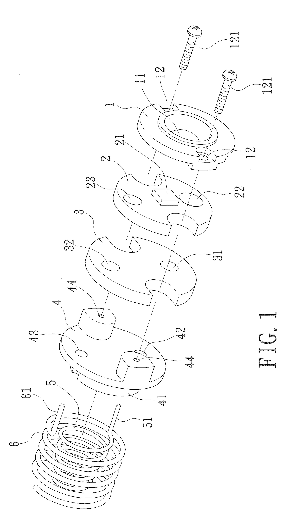
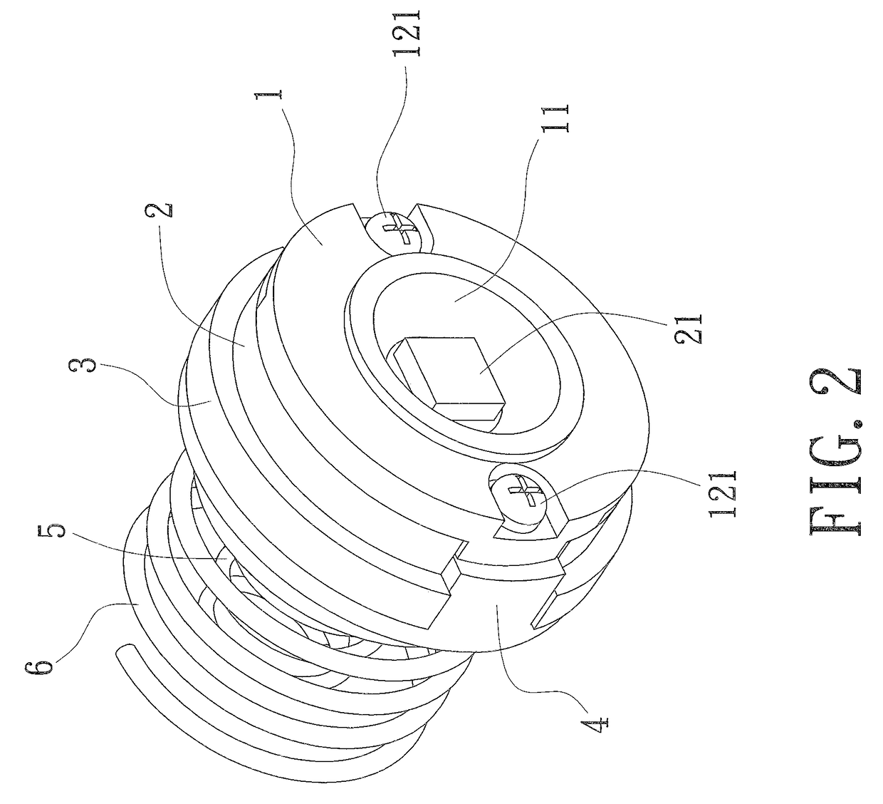
[0025]Please refer to FIG. 1, which is a three-dimensional exploded view of a light source module according to an embodiment of the present invention. A light source module comprises a fixing plate 1, a substrate 2, a heat dissipation plate 3, a fixing base 4 for elastic element, a positive electrode elastic element 5, and a negative electrode elastic element 6.

[0026]The fixing plate 1 is formed of a plastic material and formed with an aperture 11 in the center. A screw hole 12 is in an outer edge of the fixing plate 1 for a screw 121 being screwed.

[0027]The substrate 2 is set at an inner side of the fixing plate 1, connected with an illuminate element 21 at where corresponding to the aperture 11 of the fixing plate 1, and formed with a positive electrode connecting portion 22 and a negative electrode connecting portion 23 to respectively electrically connect to a positive electrode and a negative electrode of the illuminate element 21.

[0028]The heat dissipation plate 3 is formed of...


PUM


Abstract

A light source module comprises a substrate at an inner side of a fixing plate, a heat dissipation plate at an inner side of the substrate, a fixing base for elastic element at an inner side of the heat dissipation plate, a positive and a negative electrode elastic element. The substrate is connected with an illuminate element and formed with a positive and a negative electrode connecting portion for respectively connecting to the positive and negative electrodes of the illuminate element. The positive and negative electrode elastic elements are sleeved the fixing base and respectively formed with a positive and a negative electrode pin to connect to the positive and negative electrode connecting portions. Accordingly, the assembly is easier and more convenient, the bad connection or short circuit is not occurred, and the inner resistance and the power consumption are decreased.

Description

BACKGROUND OF THE INVENTIONField of the Invention[0001]The present invention relates to a light source module. More particularly, the assembly of a light source module is easier and more convenient, the bad connection or short circuit is not occurred, and the inner resistance and the power consumption are decreased, moreover, the material and the performance choice are more flexible and convenient, further decreasing the manufacture cost and increasing the utility.Description of Related Art[0002]The flashlight is a common illuminating tool in the people daily life for lighting a place which is narrow and poor visibility or dark. It is convenient for people looking for the items, walking, exercising, or doing anything. Accordingly, the flashlight is one of the necessary items in the people daily life.[0003]The present common structure of all kinds of the flashlight comprises a shell and a lampshade base. A light source module is set in front of the shell and is covered by the lampsha...

Claims


Application Information

Patent Timeline
IPC IPC(8): F21L4/00F21V23/06F21V29/70F21V29/89
CPCF21L4/005F21V29/89F21V29/70F21V23/06F21K9/20F21K9/90F21Y2101/00
Inventor LIU, YUN-ZHAO
Owner GUANGDONG JETFAST PORTABLE LIGHTING
Learn More