
Vapour compression system with at least two evaporator groups

a technology evaporator group, which is applied in the direction of mechanical equipment, refrigeration components, lighting and heating equipment, etc., can solve the problems of less energy efficient operation of evaporator group and inability to operate vapour compression system as such in appropriate manner, and achieve the effect of improving energy efficiency during the operation of vapour compression system

Active Publication Date: 2018-08-16
DANFOSS AS
View PDF4 Cites 9 Cited by
  • Summary
  • Abstract
  • Description
  • Claims
  • Application Information

AI Technical Summary

Benefits of technology

The invention is about a vapor compression system that has two evaporator groups, and it improves energy efficiency during operation compared to existing systems.

Problems solved by technology

A decrease in the ejector capacity of the ejector unit of the evaporator group will therefore result in the evaporator group being operated in a less energy efficient manner.
However, since the evaporator group is operating close to optimally, it will probably still be operating within an acceptable range, even if the ejector capacity is decreased.
In the case that several evaporator groups have operating parameters which deviate significantly from the corresponding reference values, then the vapour compression system as such may not be operating an in appropriate manner.

Method used


Image

  • Vapour compression system with at least two evaporator groups
  • Vapour compression system with at least two evaporator groups
  • Vapour compression system with at least two evaporator groups

Examples


first embodiment

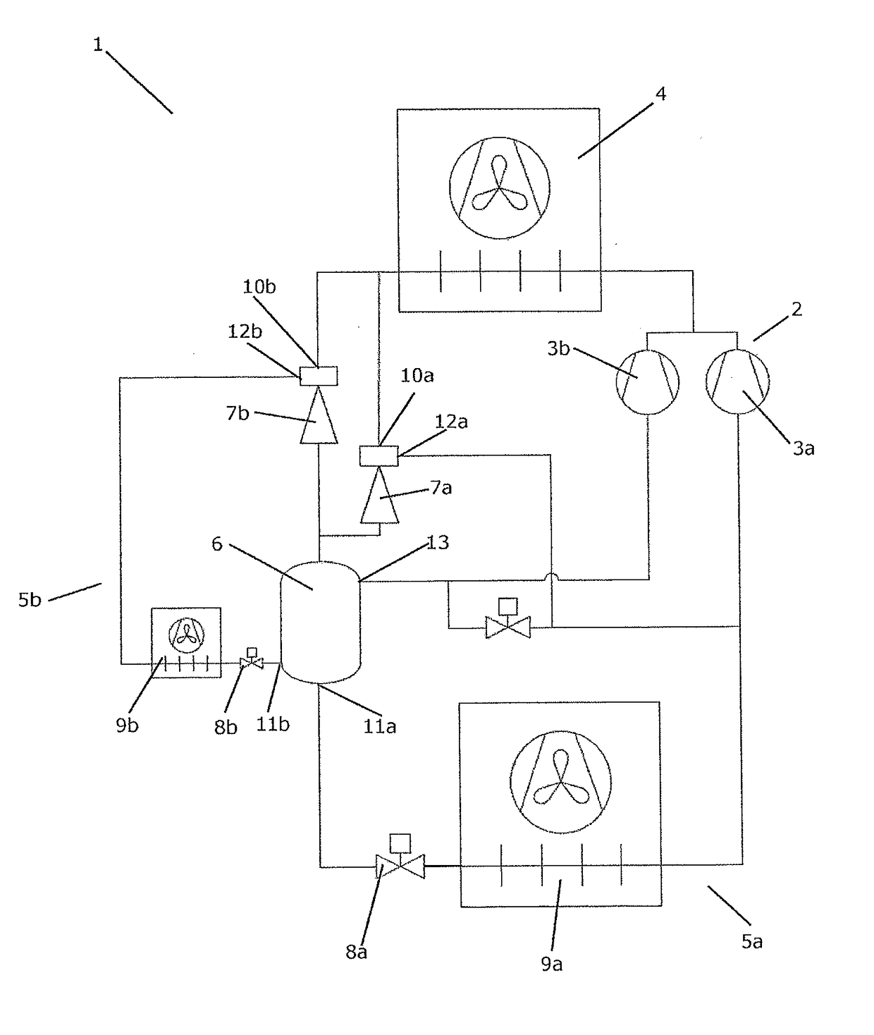
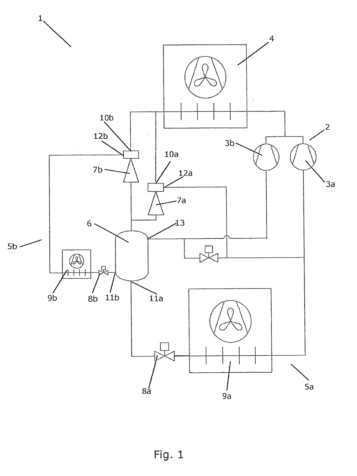
[0082]FIG. 1 is a diagrammatic view of a vapour compression system 1 according to the invention. The vapour compression system 1 comprises a compressor group 2 comprising a number of compressors 3, two of which are shown, and a heat rejecting heat exchanger 4. The vapour compression system 1 further comprises two evaporator groups 5a, 5b. The first evaporator group 5a is arranged to provide cooling for a number of cooling entities or display cases, and the second evaporator group 5b is arranged to provide air condition for one or more rooms at the facility where the cooling entities or display cases are positioned. The vapour compression system 1 further comprises a receiver 6.

[0083]The first evaporator group 5a comprises a first ejector unit 7a, a flow control device in the form of a first expansion valve 8a, and a first evaporator 9a. It should be noted that, even though the first evaporator 9a is shown as a single evaporator, it could in fact be two or more evaporators, arranged ...

second embodiment

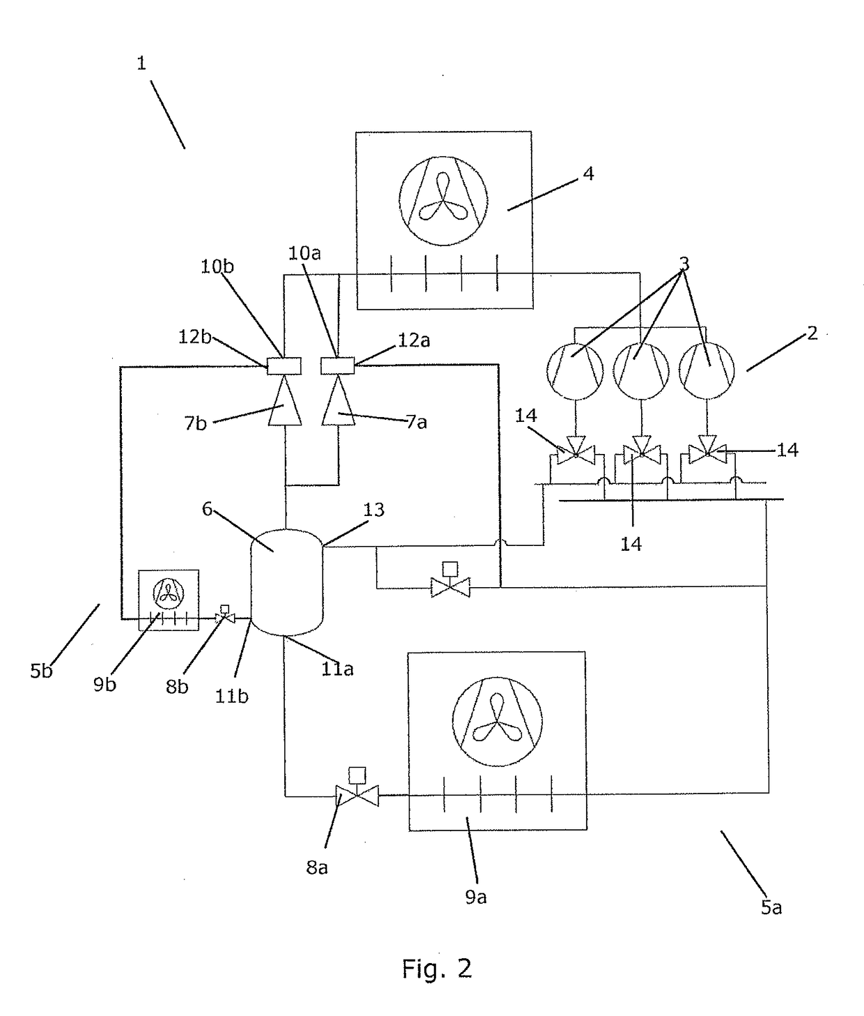
[0093]FIG. 2 is a diagrammatic view of a vapour compression system 1 according to the invention. The vapour compression system 1 of FIG. 2 is similar to the vapour compression system 1 of FIG. 1, and it will therefore not be described in detail here. In the vapour compression system 1 of FIG. 2, the compressor group 2 comprises a number of compressors 3, three of which are shown. Each of the compressors 3 is provided with a three way valve 14, allowing each of the compressors 3 to be connected to either the outlet of the first evaporator 9a or the gaseous outlet 13 of the receiver 6. Thus, the compressors 3 are not dedicated ‘main compressors’ or dedicated ‘receiver compressors’, but each compressor 3 may operate as a ‘main compressor’ or as a receiver compressor'. This allows the total available compressor capacity of the compressor group 2 to be shifted between ‘main compressor capacity’ and ‘receiver compressor capacity’, according to the current requirements, by appropriately co...

third embodiment

[0094]FIG. 3 is a diagrammatic view of a vapour compression system 1 according to the invention. The vapour compression system 1 of FIG. 3 is very similar to the vapour compression system 1 of FIG. 2, and it will therefore not be described in detail here. The vapour compression system 1 of FIG. 3 further comprises a high pressure valve 15 arranged in a part of the refrigerant path which interconnects the outlet of the heat rejecting heat exchanger 4 and the receiver 6. Thus, the high pressure valve 15 is arranged fluidly in parallel with the ejector units 7a, 7b. In the vapour compression system 1 of FIG. 3 it is therefore possible to select whether refrigerant leaving the heat rejecting heat exchanger 4 should pass through one of the ejector units 7a, 7b or through the high pressure valve 15.


PUM


Abstract

A vapour compression system (1) comprising at least two evaporator groups (5a, 5b, 5c), each evaporator group (5a, 5b, 5c) comprising an ejector unit (7a, 7b, 7c), at least one evaporator (9a, 9b, 9c) and a flow control device (8a, 8b, 8c) controlling a flow of refrigerant to the at least one evaporator (9a, 9b, 9c). For each evaporator group (5a, 5b, 5c) the outlet of the evaporator (9a, 9b, 9c) is connected to a secondary inlet (12a, 12b, 12c) of the corresponding ejector unit (7a, 7b, 7c). The vapour compression system (1) can be controlled in an energy efficient and stable manner. A method for controlling the vapour compression system (1) is also disclosed.

Description

CROSS-REFERENCE TO RELATED APPLICATION[0001]This application is a National Stage application of International Patent Application No. PCT / EP2016 / 065575, filed on Jul. 1, 2016, which claims priority to Danish Patent Application No. PA201500473, filed on Aug. 14, 2015, each of which is hereby incorporated by reference in its entirety.FIELD OF THE INVENTION[0002]The present invention relates to a vapour compression system comprising at least two evaporator groups. Each evaporator group comprises an ejector unit, and the ejector units are arranged in parallel between an outlet of a heat rejecting heat exchanger and an inlet of a receiver. The invention further relates to a method for controlling such a vapour compression system.BACKGROUND OF THE INVENTION[0003]Refrigeration systems normally comprise a compressor, a heat rejecting heat exchanger, e.g. in the form of a condenser or a gas cooler, an expansion device, e.g. in the form of an expansion valve, and an evaporator arranged in a re...

Claims


Application Information

Patent Timeline
IPC IPC(8): F25B41/06F25B49/02F25B43/00F22B3/04
CPCF25B41/062F25B49/027F25B43/006F22B3/045F25B2341/0012F25B2341/0015F25B2400/0751F25B2341/0013F25B41/00F25B49/02F25B5/02
Inventor PRINS, JANSCHMIDT, FREDEMADSEN, KENNETH BANKFREDSLUND, KRISTIAN
Owner DANFOSS AS
Learn More