
Electrical box for battery pack and battery pack structure using same

a battery pack and box body technology, applied in secondary cell servicing/maintenance, battery pack cases, cell components, etc., can solve the problems of deformation or damage of complicated external structure of the battery pack, and damage to the battery pack case or the handle, so as to improve the space utilization, improve the strength and durability, and facilitate the effect of carrying or mounting

Active Publication Date: 2018-08-16
LG ENERGY SOLUTION LTD
View PDF3 Cites 3 Cited by
  • Summary
  • Abstract
  • Description
  • Claims
  • Application Information

AI Technical Summary

Benefits of technology

This patent describes a battery pack that has a flange to support its inner frame and prevent deformation, as well as a grip rod for easy carrying and mounting. The battery pack also has a top cover with a snap-fit coupling for easy use. These features improve strength, durability, and space utilization.

Problems solved by technology

As such, since a battery pack includes a plurality of battery cells or a plurality of battery modules, a battery pack case may be deformed or damaged by a load of the battery pack itself or an external impact when the battery pack is carried or mounted.
Furthermore, as disclosed in Korean Patent Application Publication No. 10-2015-0014574, etc., existing technologies have problems in that since an additional handle is coupled to an outer surface of a battery pack case in order to carry a battery pack, an external structure of the battery pack may be complicated and the battery pack case or the handle may be damaged.
Also, as disclosed in Korean Patent Application Publication No. 10-2014-0137502, etc., existing technologies have problems in that since a handle recessed into a battery pack case is formed in order to carry a battery pack, an external structure of the battery pack may be complicated and inner space utilization may be reduced.

Method used


Image

  • Electrical box for battery pack and battery pack structure using same
  • Electrical box for battery pack and battery pack structure using same
  • Electrical box for battery pack and battery pack structure using same

Examples


Embodiment Construction

[0032]Hereinafter, embodiments of the present disclosure will be described in detail with reference to the accompanying drawings to clarify a solution to the technical problem of the present disclosure. In the description of the present disclosure, certain detailed explanations of related art are omitted when it is deemed that they may unnecessarily obscure the essence of the present disclosure. Also, terms used herein are defined in consideration of functions in the present disclosure and may be changed according to intentions of designers or manufacturers, or precedents. Accordingly, the terms used herein should be understood based on the whole content of the specification.

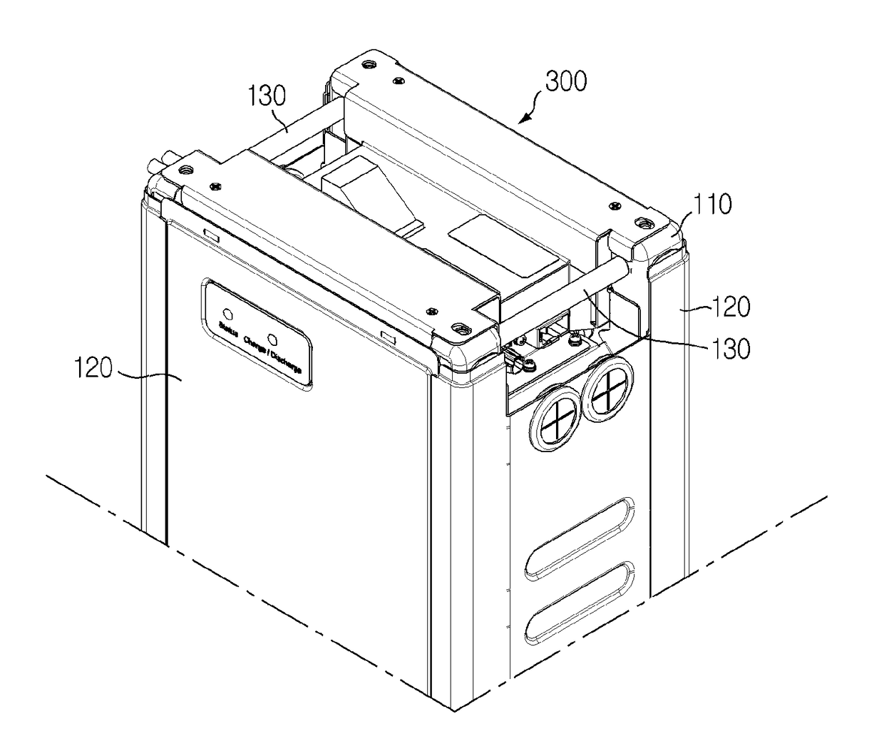
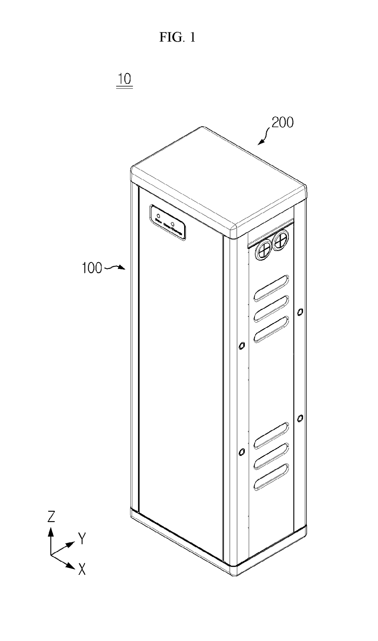
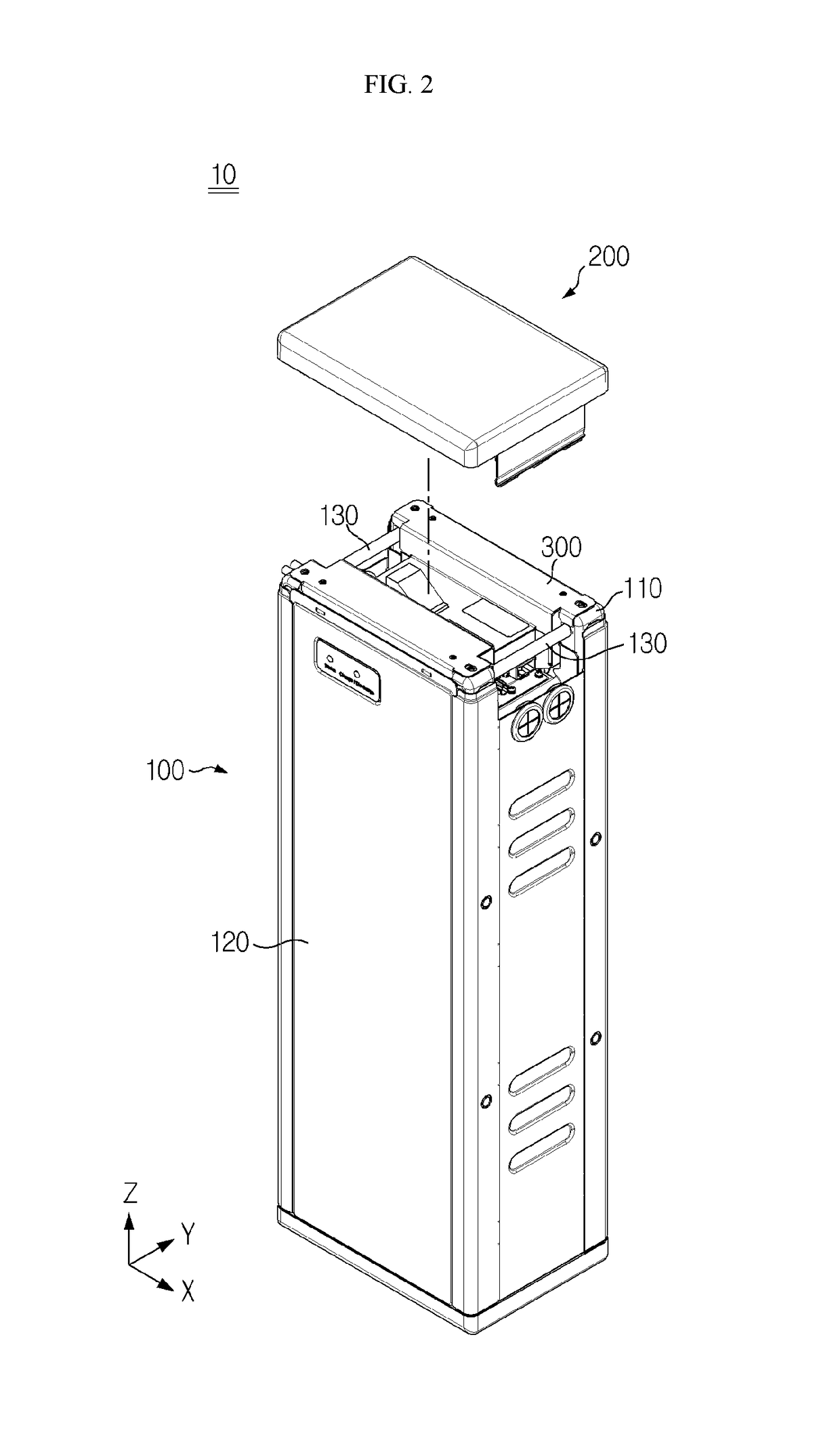
[0033]FIG. 1 is a perspective view of a battery pack structure 10 according to an embodiment of the present disclosure. FIG. 2 is a perspective view illustrating a state where a receiving case 100 and a top cover 200 of the battery pack structure 10 of FIG. 1 are separated from each other. FIG. 3 is an enlarged ...


PUM

PropertyMeasurementUnit
output voltageaaaaaaaaaa
vertical structureaaaaaaaaaa
strengthaaaaaaaaaa

Abstract

Provided are an electrical box for a battery pack and a battery pack structure using the same. The electrical box for the battery pack according to an embodiment of the present disclosure is embedded in the battery pack structure in which one or more battery modules are received and includes a battery protection circuit configured to protect the one or more battery modules, and a housing configured to receive the battery protection circuit therein, wherein the housing includes flanges that contact an inner frame constituting a load-bearing structure of the battery pack structure and are configured to support the inner frame, thereby preventing the battery pack structure from being deformed by a load of the battery pack or an external impact and improving the strength and durability of the battery pack structure.

Description

TECHNICAL FIELD[0001]The present application claims priority to Korean Patent Application No. 10-2016-0022041 filed on Feb. 24, 2016 in the Republic of Korea, the disclosure of which is incorporated herein by reference.[0002]The present disclosure relates to an electrical box for a battery pack and a battery pack structure using the same, and more particularly, to an electrical box for a battery pack which may prevent the battery pack structure from being deformed by a load of the battery pack or an external impact and may improve the strength and durability of the battery pack structure, and the battery pack structure using the electrical box.BACKGROUND ART[0003]In general, a second battery refers to a rechargeable battery such as a lithium-ion battery, a lithium-polymer battery, a nickel-cadmium battery, a nickel-hydrogen battery, or a nickel-zinc battery. Recently, as secondary batteries are applied to devices requiring a high output voltage and a high charge capacity such as ele...

Claims


Application Information

Patent Timeline
Patent Type & Authority Applications(United States)
IPC IPC(8): H01M2/10H01M10/42H02J7/00H01M50/204H01M50/262H01M50/271
CPCH01M2/1083H01M2/1094H01M10/425H02J7/0026H01M2220/20Y02E60/10H01M50/204H01M50/262H01M50/271H01M10/42H01M50/24
Inventor GANG, IN-JAELEE, BUM-HYUNKIM, HYEON-KYU
Owner LG ENERGY SOLUTION LTD
Learn More