Pseudo resistor with tunable resistance

a pseudo resistor and resistor technology, applied in the field of pseudo resistors, can solve the problems of occupying a large space, resistors with high resistance are usually larger in size, and audio band-pass filter can only achieve their bandwidth requirements, etc., and achieve the effect of expanding the scope of pseudo resistors

Active Publication Date: 2018-08-16
WINBOND ELECTRONICS CORP
View PDF6 Cites 2 Cited by
  • Summary
  • Abstract
  • Description
  • Claims
  • Application Information

AI Technical Summary

Benefits of technology

[0005]Accordingly, the invention is directed to a pseudo resistor with tunable resistance, which is capable of reducing an effect of the signal amplit

Problems solved by technology

In general, the audio band-pass filter can only achieve its bandwidth requirements by adopting a resistance with h

Method used


Image

  • Pseudo resistor with tunable resistance
  • Pseudo resistor with tunable resistance
  • Pseudo resistor with tunable resistance

Examples


Embodiment Construction

[0023]Reference will now be made in detail to the present preferred embodiments of the invention, examples of which are illustrated in the accompanying drawings. In addition, wherever possible, the same reference numbers are used in the drawings and the description to refer to the same or like parts.

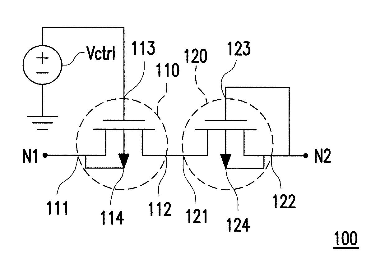
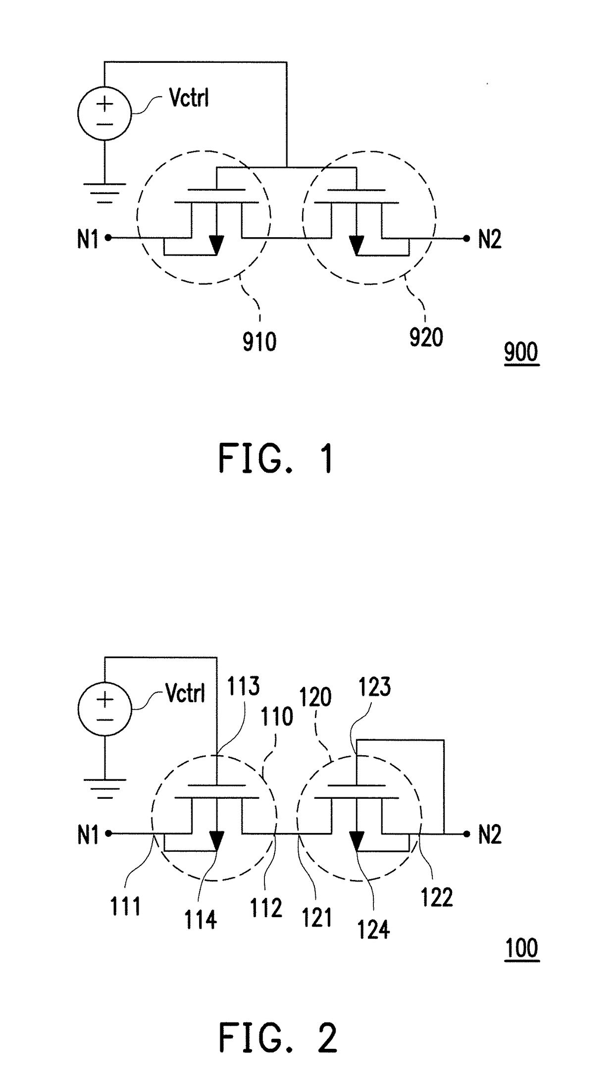
[0024]Next, with reference to FIG. 2, FIG. 2 is a schematic diagram illustrating a circuit structure of a pseudo resistor 100 with tunable resistance (referred to as the pseudo resistor 100 hereinafter) according to an embodiment of the invention. The pseudo resistor 100 includes a first transistor 110 and a second transistor 120. The first transistor 110 has a first terminal 111, a second terminal 112 and a control terminal 113. The first terminal 111 of the first transistor 110 is configured to serve as a first terminal N1 of the pseudo resistor 100. The control terminal 113 of the first transistor 110 is configured to receive a control voltage Vctrl. The first transistor 110 is contro...


PUM


Abstract

A pseudo resistor with tunable resistance including a first transistor and a second transistor is provided. The first transistor has a first terminal, a second terminal and a control terminal. The first terminal of the first transistor serves as a first terminal of the pseudo resistor. The control terminal of the first transistor receives a control voltage. The first transistor is controlled by the control voltage, such that the first transistor operates in a weak inversion region. The second transistor has a first terminal, a second terminal and a control terminal. The first terminal of the second transistor is coupled to the second terminal of the first transistor. The second terminal of the second transistor and the control terminal of the second transistor are coupled to each other to serve as a second terminal of the pseudo resistor with tunable resistance. The second transistor operates in the weak inversion region.

Description

CROSS-REFERENCE TO RELATED APPLICATION[0001]This application claims the priority benefit of China application serial no. 201710076077.0, filed on Feb. 13, 2017. The entirety of the above-mentioned patent application is hereby incorporated by reference herein and made a part of this specification.BACKGROUND OF THE INVENTION1. Field of the Invention[0002]The invention relates to a pseudo resistor, and more particularly, to a pseudo resistor with tunable resistance.2. Description of Related Art[0003]In the technical field of medical electronics, signals received by medical equipments belong to a physiological signal in audio fashion. An audio band-pass filter at a receiver of the medical equipment needs to reliably filter out low frequency noises in the received signals in order to accurately capture the physiological signal for use in subsequent analysis and process. In general, the audio band-pass filter can only achieve its bandwidth requirements by adopting a resistance with high i...

Claims


Application Information

Patent Timeline
IPC IPC(8): H03H11/24
CPCH03H11/245H03H11/53H03F2203/45524
Inventor HUNG, CHUNG-CHIHCHANG, JIA-HENG
Owner WINBOND ELECTRONICS CORP
Why Eureka
Try Eureka