
Polishing holder mounting jig and optical fiber ferrule polishing holder

a technology of polishing holder and polishing holder, which is applied in the direction of manufacturing tools, lapping machines, instruments, etc., can solve the problems of labor and time required to attach difficult to quickly and easily remove the optical fiber ferrule polishing holder from the optical fiber ferrule polishing machine, and achieve the effect of easy release, fast and easy attachment of the optical fiber ferrule polishing holder to the optical fiber ferrule polish

Inactive Publication Date: 2018-08-23
SEIKOH GIKEN
View PDF14 Cites 5 Cited by
  • Summary
  • Abstract
  • Description
  • Claims
  • Application Information

AI Technical Summary

Benefits of technology

The present invention provides a polishing holder mounting jig that can quickly and easily attach and remove the optical fiber ferrule polishing holder from the polishing machine without requiring excessive labor. The jig has a holder plate with installation units evenly spaced around the edges, and an attaching plate attachment to the holder plate allows for even polishing of multiple optical fiber ferrules. The jig's rear end portion extends through the installation units and is positioned to not interfere with them. The exposed end portion of the handle shaft can easily release its engagement with the central recess of the mounting shaft. The technical effects of the invention are quick and easy attachment and removal of the polishing holder, and efficient and even polishing of multiple optical fiber ferrules.

Problems solved by technology

Thus, labor and time are required to attach the optical fiber ferrule polishing holder to the optical fiber ferrule polishing machine and remove the optical fiber ferrule polishing holder from the optical fiber ferrule polishing machine.
Eventually, it is difficult to quickly and easily attach the optical fiber ferrule polishing holder to the optical fiber ferrule polishing machine, and also it is difficult to quickly and easily remove the optical fiber ferrule polishing holder from the optical fiber ferrule polishing machine.

Method used


Image

  • Polishing holder mounting jig and optical fiber ferrule polishing holder
  • Polishing holder mounting jig and optical fiber ferrule polishing holder
  • Polishing holder mounting jig and optical fiber ferrule polishing holder

Examples


Embodiment Construction

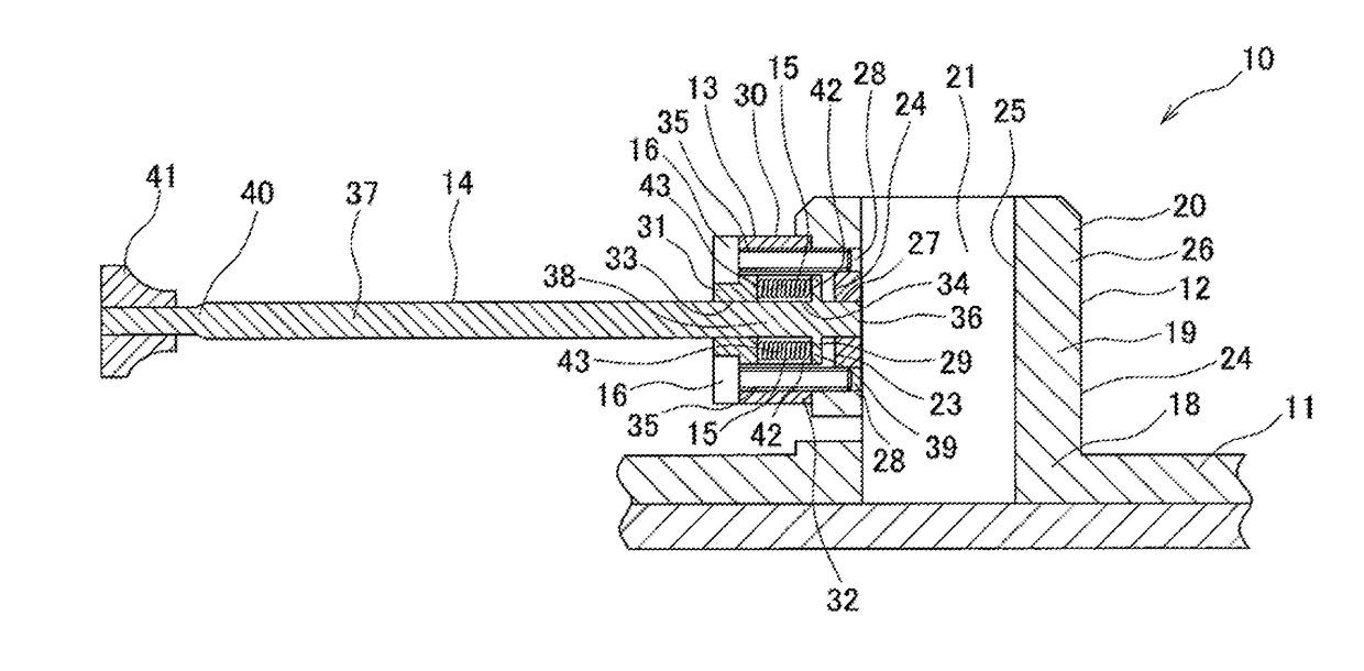
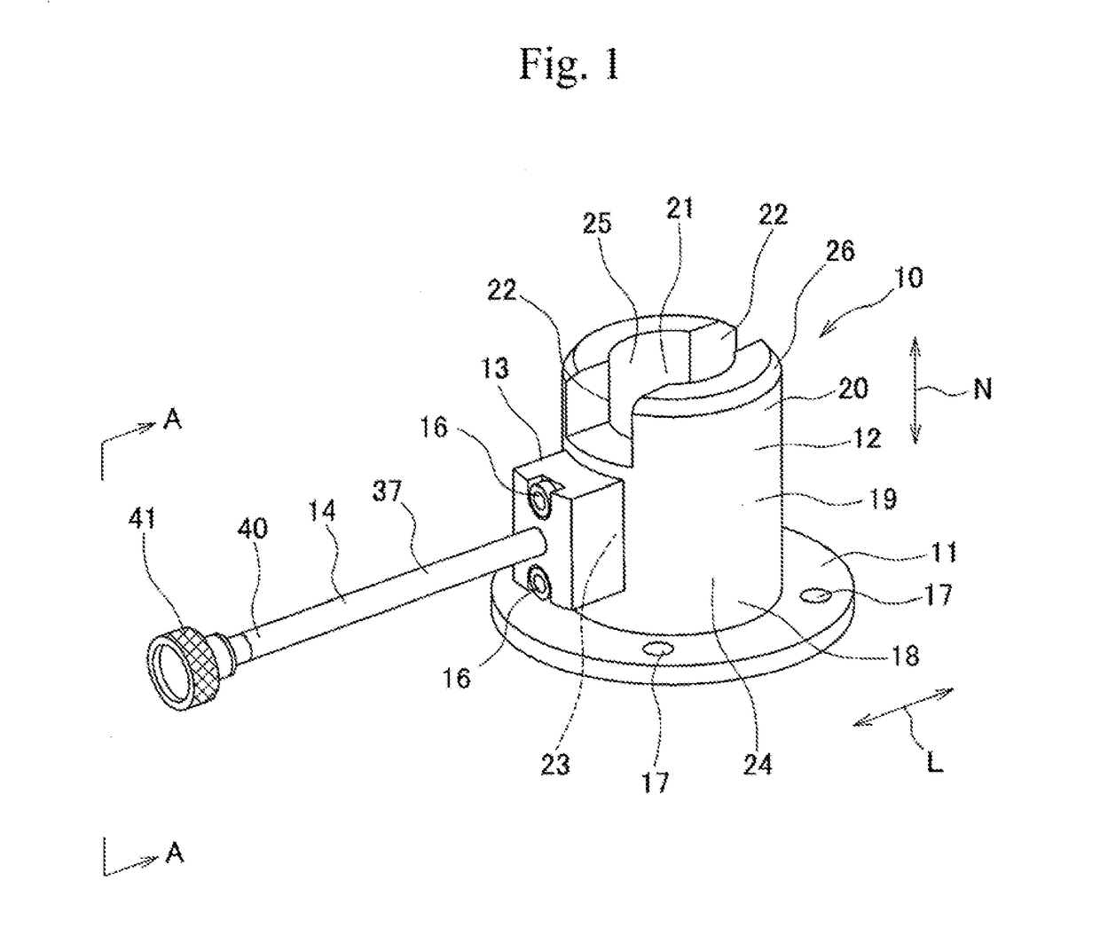
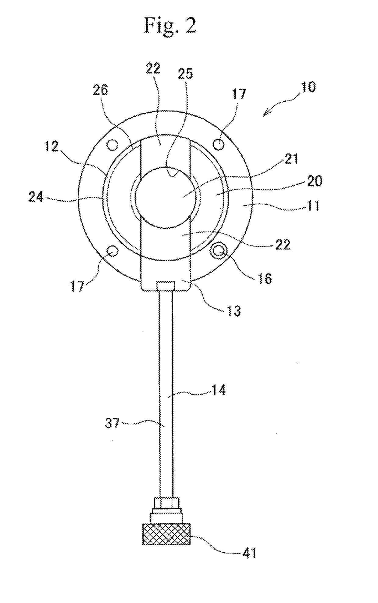
[0049]The polishing holder mounting jig according to the present invention and the optical fiber ferrule polishing holder according to the present invention will be described in detail with reference to the accompanying drawings of FIG. 1 and the like. FIG. 1 is a perspective view of the polishing holder mounting jig shown as an example. FIG. 2 is a top view of the polishing holder mounting jig and FIG. 3 is a cross-sectional view taken along line A-A in FIG. 1. FIG. 4 is a cross-sectional view which is the same as FIG. 3 except that a handle shaft of an operating rod is moved outward in a radial direction. In FIG. 1, a radial direction is indicated by an arrow L and a vertical direction is indicated by an arrow N.

[0050]A polishing holder mounting jig 10 is detachably attached to an optical fiber ferrule polishing holder 50 (shown in FIG. 5) used for polishing optical fiber ferrules 101a. The polishing holder mounting jig 10 is used for attaching the optical fiber ferrule polishing ...


PUM


Abstract

A polishing holder mounting jig 10 is configured to mount an optical fiber ferrule polishing holder 50 to a mounting shaft 104 of an optical fiber ferrule polishing machine 103 when the mounting shaft 104 of the optical fiber ferrule polishing machine 103 is inserted into an insertion space of an insertion pipe 12, the exposed end portion 36 is moved gradually outward in a radial direction along a tip inclined face 108 against a biasing force of a coil spring 15, the exposed end portion 36 is slid on an outer peripheral surface of the mounting shaft 104 until the exposed end portion 36 reaches a central recess 109, and the exposed end portion 36 is moved inward in the radial direction toward the central recess 109 by the biasing force of the coil spring 15 until the exposed end portion 36 is exposed to the central recess 109.

Description

CROSS-REFERENCES TO RELATED APPLICATIONS[0001]This patent specification is based on Japanese patent application, No. 2017-029160 filed on Feb. 20, 2017 in the Japan Patent Office, the entire contents of which are incorporated by reference herein.BACKGROUND OF THE INVENTION1. Field of the Invention[0002]The present invention relates to a polishing holder mounting jig for attaching an optical fiber ferrule polishing holder to an optical fiber ferrule polishing machine, and also relates to the optical fiber ferrule polishing holder used for polishing the optical fiber ferrules.2. Description of the Related Art[0003]Patent Document 1 discloses an optical fiber ferrule polishing holder comprised of: a holder plate; seats; and supporting walls, wherein the holder plate has a plurality of ferrule insertion holes into which a plurality of optical fiber ferrules is inserted, the seats have a wall surface spaced at a predetermined distance from the insertion holes, the seats extend along one ...

Claims


Application Information

Patent Timeline
Patent Type & Authority Applications(United States)
IPC IPC(8): B24B19/22G02B6/46
CPCB24B19/226G02B6/46B24B37/27B24B37/34B24B41/067G02B6/3863
Inventor SHIBUTANI, YUJI
Owner SEIKOH GIKEN
Learn More