Method and apparatus in a pneumatic pipe transport system for material, and a conveying system for wastes

a technology of conveying system and transport system, which is applied in the direction of bulk conveyors, household applications, refuse gathering, etc., can solve the problems of large space requirement of intermediate containers, high excavation costs, and inability to meet the requirements of material transportation, so as to enhance the efficiency of displacing material, prevent material displacement, and efficiently regulate

Active Publication Date: 2018-08-23
MARICAP OY
View PDF1 Cites 4 Cited by
  • Summary
  • Abstract
  • Description
  • Claims
  • Application Information

AI Technical Summary

Benefits of technology

[0012]The invention is based on a concept wherein a bypass channel is arranged in the channel section of the intermediate container of an input point for compensating a change in volume resulting from a pressure difference of the intermediate container of the input point. The bypass channel is also utilized for conducting possible leakage air of the input point into the material conveying pipe past the material that has been fed into intermediate container. The aforementioned are applied e.g. in cases in which it is not intended to empty the intermediate container of an input point. A bypass channel can also be used for conducting replacement air when it is desired to empty the intermediate container of the input point. Material fed into an intermediate container can form a piston-like plug when it compacts in the intermediate container, in which case, owing to the bypass channel, the change in volume of the material resulting from the pressure difference of an intermediate container of an input point, as well as the combined effect of possible leakage air of the input point plus the suction acting from the conveying pipe on the material that has been fed into the intermediate container and is trying to displace, can be avoided when it is not intended to displace the material with the combined effect of replacement air and suction.
[0018]The solution according to the invention has a number of important advantages. By means of the invention a change in volume, and the drawbacks associated with it, of the material of the intermediate container of the channel section can be compensated. By means of the invention the displacement in an undesired manner of material that is in the intermediate container of a channel section from the intermediate container into the material conveying pipe can be avoided. When the material forms a plug, similar to a piston, in an intermediate container, the displacement of material can be prevented with the bypass channel by compensating the pressure difference in the channel space on different sides of the material that has been fed into it, and possibly also by conducting leakage air in the bypass channel from the channel space, from the first side of the material, i.e. from the input aperture side, into the channel space, to the second side of the material, i.e. to the conveying pipe side. This is advantageous in particular when the intermediate containers of other input points are emptied, when suction is acting in the channel space from the conveying pipe side. In this case the mixing together of different categories of waste material in the conveying pipe is avoided. A bypass channel can also be used for conducting replacement air to the delivery end of the intermediate container of a channel part, when the actual replacement air valve of an input point or channel part has been opened and it is desired that the material of the intermediate container starts to move into the actual conveying pipe and be conducted onwards to the delivery end of the pneumatic conveying system for material, into a separating device and / or into a waste container. According to one embodiment the bypass channel can be formed to be smaller in its flow cross-sectional area than the flow cross-sectional area of the channel space. According to one embodiment the cross-sectional area of the bypass channel is preferably approx. 10-25% of the cross-sectional area of the material conveying pipe, such as of the waste pipe. The bypass channel can be formed into a pipe section arranged outside the channel space of the actual intermediate container. According to one embodiment the channel parts formed by the intermediate container and the bypass channel are integrated into one structural element. By arranging an expansion and a suitable screen part for it in the channel part at the point connecting to the first end of the bypass channel, the passage of large-sized particles into the bypass channel can be avoided and an operationally reliable pathway from the top part of the channel part into the bypass channel is achieved for leakage air or for some of the replacement air.
[0019]According to one embodiment a connection point is arranged in the bypass channel, e.g. for connecting a cleaning means or a suction / blowing means to the bypass channel, in which case an effective arrangement for cleaning the bypass channel, if necessary, is obtained. According to one preferred embodiment the connection point of the bypass channel is provided with a plug. The solution according to the invention is well suited to both small and large systems. The invention is suited to material conveying systems in which suction and replacement air are used together for moving material and in which a separate discharge valve is not used between the intermediate container of an input point and the material conveying pipe. In addition, the bypass channel can also be used for conducting some of the replacement air to the end of the intermediate container on the actual conveying pipe side. The invention can be applied in connection with many types of intermediate containers. An intermediate container can e.g. be disposed in a horizontal attitude or it can comprise a horizontal section, in which case a deep installation pit is not needed for it, but instead a conventional excavation depth can be used for the waste conveying piping. By arranging the channel section of the intermediate container of one material category to be such that the channel sections of the intermediate container of at least one other input point, typically of all the input points, of the feed-in station connect to it, a collection piping assembly is achieved wherein the intermediate container of the material category requiring most intermediate container volume can be formed, on the one hand, in a shallow space, but however large in volume. In this case the number of input points for the material category can at the same time be limited. The entry of replacement air in the material conveying phase can be regulated e.g. with a separate replacement air valve arranged in the container part of an input point. By opening and closing the replacement air valve, the start of movement of material in the intermediate container can be efficiently regulated when the suction side of the partial-vacuum source is connected to act in the channel section from the direction of the conveying pipe. By using a bypass channel for conducting also replacement air, replacement air can be brought into the body of material to be displaced from the intermediate container, which enhances the efficiency of displacing material in the conveying pipe.

Problems solved by technology

One drawback, among others, of known solutions is that the space requirement of an intermediate container, especially when an input pipe is used as an intermediate container, is large.
The excavation work is expensive, particularly in rocky areas where blasting is required for achieving the trench needed.
The excavation work is expensive, particularly in rocky areas where blasting is required for achieving a trench.
A problem that arises in cases in which a separate discharge valve, i.e. waste valve, is not used is that the material can travel in an undesired manner into the material conveying pipe as a result of a pressure difference between an input point and the material conveying pipe and / or possible leakage air of an input point.

Method used


Image

  • Method and apparatus in a pneumatic pipe transport system for material, and a conveying system for wastes
  • Method and apparatus in a pneumatic pipe transport system for material, and a conveying system for wastes
  • Method and apparatus in a pneumatic pipe transport system for material, and a conveying system for wastes

Examples


Embodiment Construction

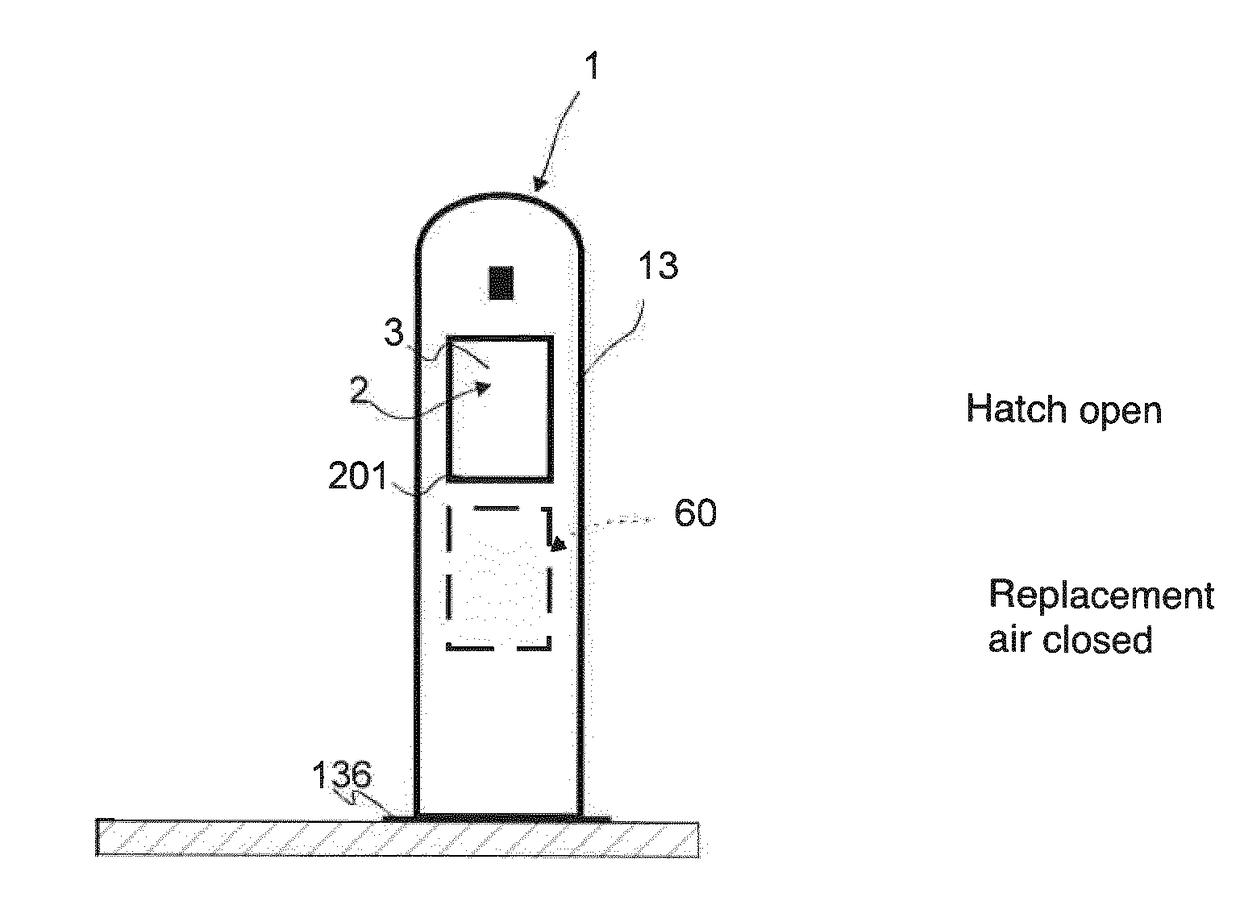
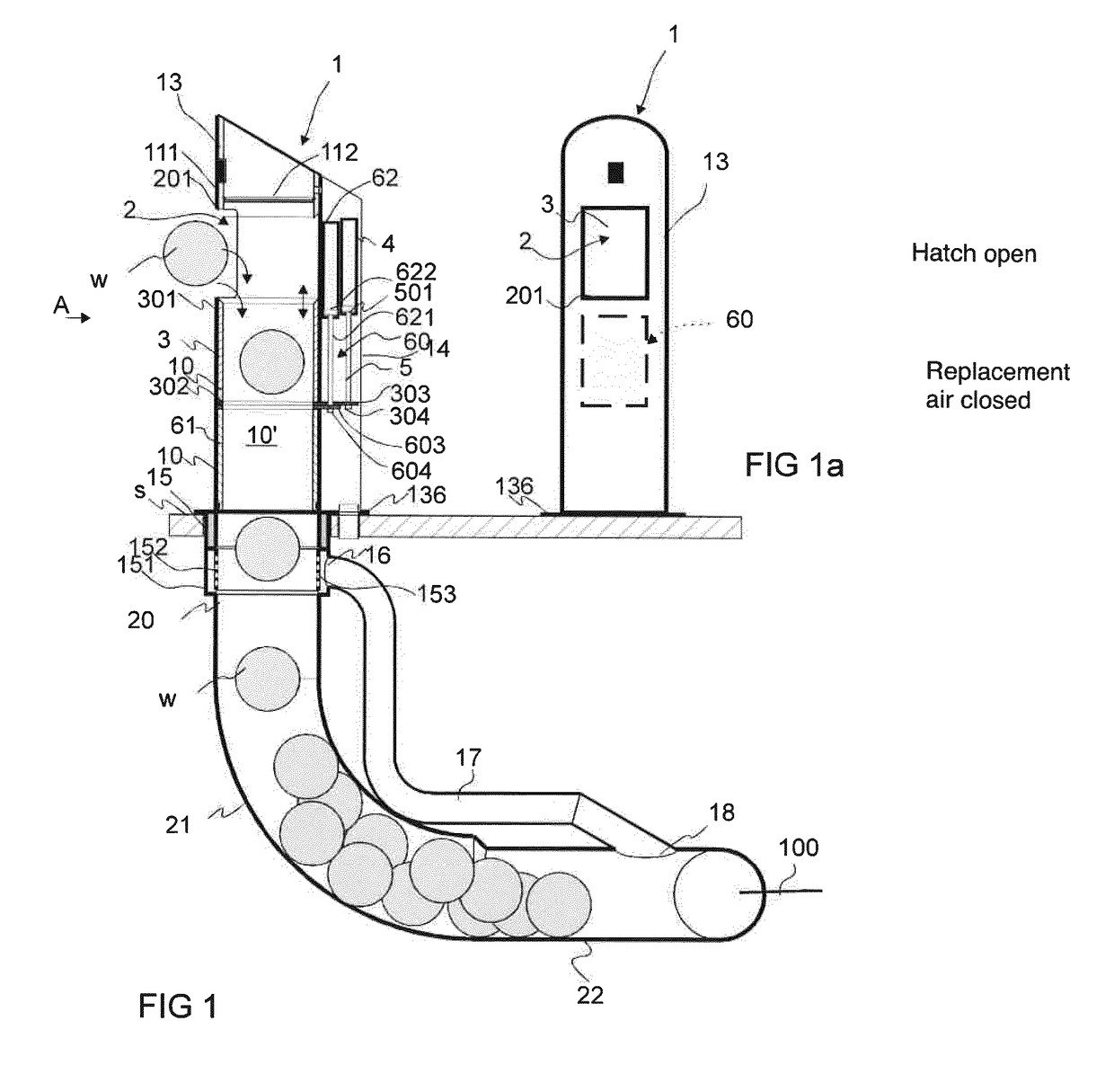
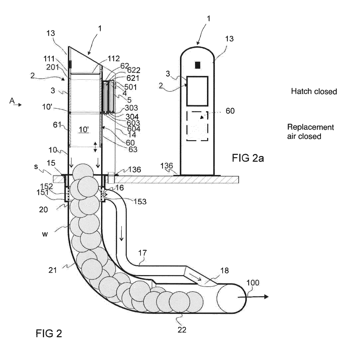
[0038]FIGS. 1-4 present a simplified view of an apparatus according to the invention in connection with one input point 1 and its intermediate container. The apparatus is intended to connect a pneumatic material conveying system to a material conveying pipe 100 (marked diagrammatically with an arrow at the starting end of the conveying pipe only) and via the conveying pipe to a separating device and to a partial-vacuum generator, such as a vacuum pump or fan, of the pneumatic material conveying system, the suction side of which partial-vacuum generator can be connected to a separating device and via it to conveying piping and onwards via a conveying pipe through channel parts to act in the material space of the input point and of the intermediate container.

[0039]FIGS. 1-4 describe in a simplified manner the operation of the input points. In each input point 1 is an input aperture 2 for feeding material w, such as waste material or recyclable material, into a feed-in container 10 of ...


PUM


Abstract

Method for compensating a change in volume caused by a pressure difference of the intermediate container of an input point of a pneumatic pipe collection system for material and / or for preventing undesired material displacement from the intermediate container. In the method a bypass channel is arranged in the channel section formed by the intermediate container of an input point for compensating a change in volume resulting from the pressure difference of the pressures of different magnitudes possibly acting on different sides of the material and / or for preventing undesired material displacement from the channel section into the material conveying pipe. The invention also relates to an apparatus and to a wastes conveying system.

Description

FIELD OF THE INVENTION[0001]The object of the invention is a method as defined in the preamble of claim 1.[0002]The object of the invention is also an apparatus as defined in claim 11.[0003]The invention also relates to a system as defined in claim 21.BACKGROUND OF THE INVENTION[0004]The invention relates generally to material conveying systems, such as to pneumatic partial-vacuum transporting systems, more particularly to the collection and conveying of wastes, such as to the conveying of household wastes. Such systems are presented in publications WO 2009 / 080880, WO 2009 / 080881, WO 2009 / 080882, WO 2009 / 080883, WO 2009 / 080884, WO 2009 / 080885, WO 2009 / 080886, WO 2009 / 080887 and WO 2009 / 080888, among others. The invention also relates to waste feeding means, such as to input points or refuse chutes, with which waste is conveyed, typically by gravity, e.g. from higher input apertures in residential buildings to a lower collection space or corresponding container.[0005]Systems wherein ...

Claims


Application Information

Patent Timeline
Patent Type & Authority Applications(United States)
IPC IPC(8): B65F5/00B65G53/52
CPCB65F5/005B65G53/521B65G53/40B65F5/00
Inventor SUNDHOLM, GORAN
Owner MARICAP OY
Why Eureka
Try Eureka