Stent

a technology of stents and stents, which is applied in the field of endovascular devices, can solve the problems of inability to effectively use hydrogels in this way, unfavorable, and inability to apply covered stents to neuronal structures, and achieve the effect of reducing fabrication efforts and simple design

Inactive Publication Date: 2018-08-30
WALZMAN DANIEL EZRA
View PDF3 Cites 4 Cited by
  • Summary
  • Abstract
  • Description
  • Claims
  • Application Information

AI Technical Summary

Benefits of technology

[0012]The present invention is a simple design and is mechanical in nature. Said design may be fabricated from two nearly identical elements. Th

Problems solved by technology

The ability to effectively use hydrogel in this way remains an unproven technology, and may not be feasible.
The prior art has also attempted to apply covered stents to neuro applica

Method used


Image

  • Stent
  • Stent
  • Stent

Examples


Embodiment Construction

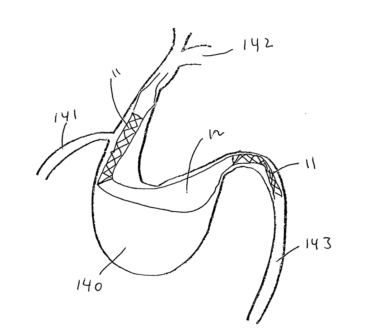
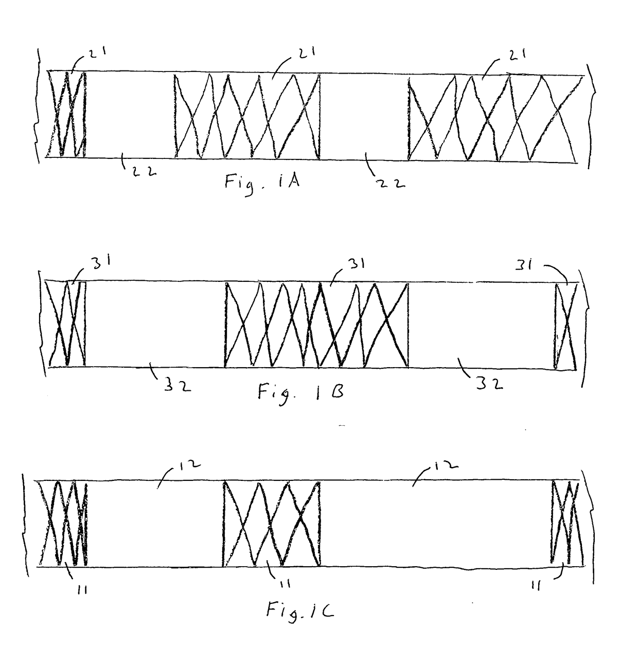
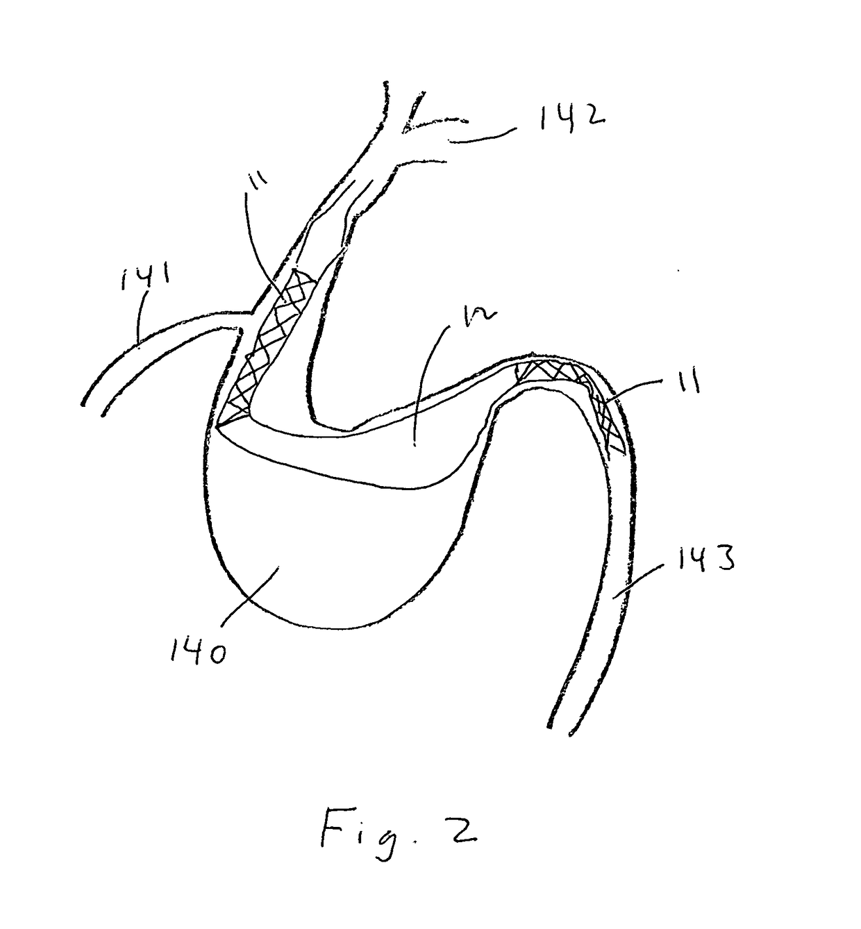
[0018]Referring now to FIG. 1, the present invention (10) is composed of at least two corresponding, cylindrically shaped stent bodies (20, 30). Now referring to FIG. 1A, the present invention includes at least one cylindrically shaped stent body (20) composed of covered (22) and uncovered (21) zones. Now referring to FIG. 1B, the present invention also includes at least a second cylindrically shaped body is also composed of covered (32) and uncovered (31) zones. The diameter of said second cylindrical stent body (30) is dimensioned such that said first cylindrical stent body (20) may be inserted snugly therethrough following placement of said second stent body (30) at a target aneurysm or other designated location within a the lumen of a blood vessel.

[0019]Referring to FIG. 1C, when first cylindrically shaped body (20) is inserted inside second cylindrically shaped body (30), covered (22, 32) and uncovered (21, 31) zones overlap. Whenever two uncovered zones (21, 31) coincide as sh...


PUM

PropertyMeasurementUnit
Polymericaaaaaaaaaa

Abstract

The present invention teach an overlapping covered stents with uncovered segments capable of effectively diverting blood flow away from an aneurysm or fistula while allowing blood to flow to its normal vascular territory of healthy tissue distal to the targeted treatment area and still resulting in blood stasis and thrombus formation inside the aneurysm or fistula.

Description

BACKGROUND OF THE INVENTIONField of the Invention[0001]The present disclosure relates to medical devices used to treat aneurysms and fistulas within unhealthy blood vessels, and more particularly, relates to endovascular devices.Background Art[0002]The prior art teaches the use of a number devices to treat aneurysms. A common blood vessel difficulty is the persistent blood flow in the aneurysm sac extrinsic to the endograft. In fact, this is the most common complication after endovascular aneurysm repair (EVAR). Such endoleaks are ameliorated by a number of means. For example, Walzman's 15 / 732,147 and 15 / 732,365 teach the use of hydrogel to prevent endoleaks.[0003]The prior art also teaches endovascular coiling as a minimally invasive technique performed to prevent blood from flowing into an aneurysm. This treatment results in the coil inducing embolization (clotting) of the aneurysm, which prevents blood from flowing into the aneurysm, which in turn, prevents subarachnoid hemorrhag...

Claims


Application Information

Patent Timeline
IPC IPC(8): A61F2/852A61F2/91A61L31/12A61L31/14A61L31/02A61L31/04
CPCA61F2/852A61F2/91A61L31/125A61L31/146A61L31/022A61L31/04A61F2002/823A61F2002/826A61F2220/0033A61F2250/0063A61B17/12031A61B17/12113A61B17/12172A61B17/12177A61B2017/00893A61B2017/00898A61L31/10A61L31/14A61L31/145A61L31/16C08L27/18A61B2090/3966A61B17/12122A61B17/1214A61B17/1219A61B17/22032A61B17/320758A61B2017/00477A61B2017/00867A61B2017/1205A61B2017/1209A61B2017/320716A61B2217/005A61B2217/007A61L29/145A61L29/16A61L2430/06A61M25/10A61M2025/0057A61M2210/125
Inventor WALZMAN, DANIEL EZRA
Owner WALZMAN DANIEL EZRA
Why Eureka
Try Eureka