Electric vehicle braking system, method, controller and computer program product

a technology for electric vehicles and braking systems, applied in the direction of braking systems, electric vehicles, electrodynamic brake systems, etc., can solve the problems of inefficient energy generation, non-optimal braking, and inefficient braking, so as to maximize energy generation

Active Publication Date: 2018-08-30
JAGUAR LAND ROVER LTD
View PDF5 Cites 10 Cited by
  • Summary
  • Abstract
  • Description
  • Claims
  • Application Information

AI Technical Summary

Benefits of technology

[0014]The vehicle condition is thus used to determine a brake force distribution range which defines maximum braking distribution threshold associated with the, or each, axle. By maximum braking distribution threshold we mean the braking distribution above which the surface adhesion is exceeded. In this way, the braking force of the respective axle will not exceed a maximum force associated with the stability of the vehicle so as not to over-steer or under-steer.
[0015]In an embodiment, the output may be arranged to send a signal to configure the braking system to re

Problems solved by technology

However, during regenerative braking, the process is reversed and the shaft is decelerated by resistance in using the electric machine as a generator to convert the mechanical energy of the shaft rotation into electrical energy.
In this way, the energy recovered during regenerative braking is not optimised since during the life of the vehicle, various components,

Method used


Image

  • Electric vehicle braking system, method, controller and computer program product
  • Electric vehicle braking system, method, controller and computer program product
  • Electric vehicle braking system, method, controller and computer program product

Examples


Embodiment Construction

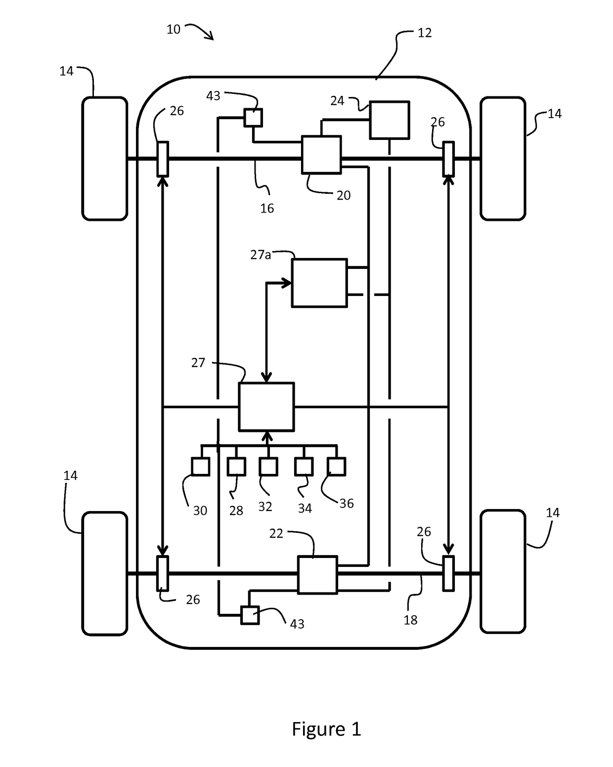
[0040]With reference to FIG. 1, a vehicle 10 includes a body 12 driven by a set of wheels 14. The wheels 14 support the body on respective front and rear axles 16, 18.

[0041]The vehicle in this embodiment is an electric vehicle, though this invention is also applicable to hybrid electric vehicles. The electric vehicle 10 includes a front machine 20 on the front axle 16 and a rear machine 22 on the rear axle 18. Alternatively, the vehicle 10 may include more than one machine on each axle 16, 18, for instance one machine on each side shaft, or expressed differently, one machine per wheel. Each machine is operable to act as a motor for converting electrical energy into kinetic energy for powering the respective axle. In addition, each machine is operable to act as a generator for converting kinetic energy recovered during a braking event into electrical energy. The electrical energy is stored in a battery 24.

[0042]The vehicle 10 also includes hydraulic braking provisions in the form of ...


PUM


Abstract

The present invention relates to a controller (27) for a braking system for a vehicle (10). The braking system has an independent generator (20, 22) on respective front and rear axles (16, 18). The controller (27) comprises an input (44) arranged to monitor a vehicle condition and an operating condition of the generators (20, 22). The controller (27) also comprises a processing means (46) arranged to determine a brake force distribution range between the front and rear axles (16, 18) based on the vehicle condition, and in response to a braking demand and the operating condition of the generators (20, 22), calculate a brake force distribution within the brake force distribution range. In addition, the controller (27) comprises an output (50) arranged to control the generators in accordance with the calculated brake force distribution.

Description

TECHNICAL FIELD[0001]The invention relates to a regenerative braking system and more particularly, but not exclusive, to those regenerative braking systems of an electric or hybrid electric vehicle having an independent generator on each axle. Aspects of the invention relate to a controller for a braking system, a braking system, a vehicle, and a method of operating a braking system of a vehicle.BACKGROUND[0002]A vehicle can be decelerated, or retarded, using a braking system. Typically a braking system includes a hydraulic braking system. In more recent times, braking systems have also incorporated regenerative braking systems.[0003]A hydraulic braking system typically includes disc brakes for decelerating each wheel of the vehicle. These disc brakes include a brake disc, or rotor, mounted to a side shaft of the vehicle and a pair of brake pads supported in a caliper to position the brake pads either side of the brake disc. A hydraulic circuit is provided to apply pressure to each ...

Claims


Application Information

Patent Timeline
IPC IPC(8): B60L7/26B60T8/172B60T8/1755B60T8/30B60T8/32B60T8/58B60L7/18B60L15/20
CPCB60L7/26B60T8/172B60T8/17551B60T8/17552B60T8/30B60T8/3205B60T8/58B60L7/18B60L15/2009B60T2270/604B60T2270/613B60T2250/03B60T2210/12B60T2220/04B60T8/1766B60T2270/60Y02T10/64Y02T10/72B60T8/17B60W10/08B60W10/184
Inventor SATTERTHWAITE, ANTHONYHANCOCK, MATTHEWHEGARTY, SIMONGODLEWSKI, NICOLASISMAIL, ZAHIR
Owner JAGUAR LAND ROVER LTD
Why Eureka
Try Eureka