Method for controlling a wave power system by means of a control obtained by minimizing an objective function weighted and discretized by the trapezoidal rule

a control method and wave power technology, applied in the direction of sea energy generation, mechanical equipment, machines/engines, etc., can solve the problems of not optimal, unable to achieve optimal control which maximizes recovered energy, and methods that do not account for energy losses, so as to maximize the average power recovered, maximize the energy generated, and improve the operation of the wave energy system

Active Publication Date: 2021-09-07
INST FR DU PETROLE
View PDF13 Cites 0 Cited by
  • Summary
  • Abstract
  • Description
  • Claims
  • Application Information

AI Technical Summary

Benefits of technology

[0008]To overcome these drawbacks, the present invention improves the operation of a wave energy system by use of a converter predictive control method that maximizes the energy generated by accounting for the energy conversion efficiency and of a wave prediction. Furthermore, the method according to the invention determines the optimal control by minimizing an objective function weighted and discretized by the trapezoidal rule. Thus, the control method according to the invention allows determining the control that maximizes the average power recovered with reduced computation times, because optimization of the discretized and weighted objective function leads to a strictly convex quadratic programming problem, which can be solved with very efficient algorithms.
[0017]iv) deducing the control value from the force exerted by the converter machine on the mobile device by minimizing the discretized and weighted objective function; and
[0025]{x.⁡(t)=Ac⁢x⁡(t)+Bcu⁢u⁡(t)+Bcw⁢w⁡(t)y⁡(t)=Cc⁢x⁡(t),with x being the state vector of the wave energy system with the converter machine, u being the control of the force exerted by the converter machine on the mobile device, w being the excitation force of the incident waves on the mobile device, Ac, Bcu, Bcw, and Cc being matrices multiplying the state, and the inputs of the dynamic model allowing calculation of the dynamic variation of the state and the outputs of the dynamic model.

Problems solved by technology

Some are not optimal because the wave motion prediction is not taken into consideration.
Furthermore, these methods do not account for the energy losses upon energy conversion in the wave energy system.
However, these algorithms do not allow the energy losses upon energy conversion in the wave energy system to be taken into account, which does not enable an optimal control which maximizes the recovered energy.
On the other hand, long and complex calculations are necessary to obtain the optimal solution, which can make real-time implementation on the wave energy system difficult or even impossible, depending on the power of the available control calculator.
The computational complexity is due to the non-convexity of the quadratic objective function which, coupled with a large number of unknowns, requires using a large-scale non-linear optimization algorithm.

Method used


Image

  • Method for controlling a wave power system by means of a control obtained by minimizing an objective function weighted and discretized by the trapezoidal rule
  • Method for controlling a wave power system by means of a control obtained by minimizing an objective function weighted and discretized by the trapezoidal rule
  • Method for controlling a wave power system by means of a control obtained by minimizing an objective function weighted and discretized by the trapezoidal rule

Examples


application example

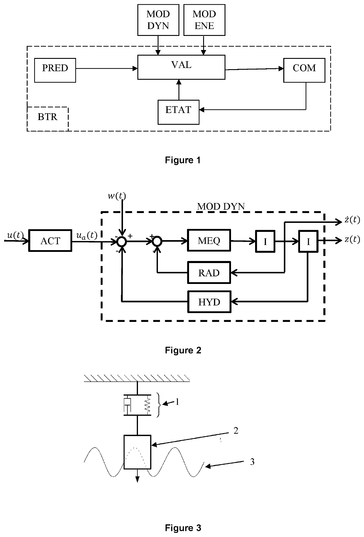
[0231]A non-limiting example of a wave energy system is an oscillating buoy as shown in FIG. 3. This wave energy system comprises a buoy 2 as the mobile device of mass m, a converter machine 1 of damping d and elasticity k that is stationary. The buoy is subjected to an oscillating motion through waves 3 and to hydraulic forces.

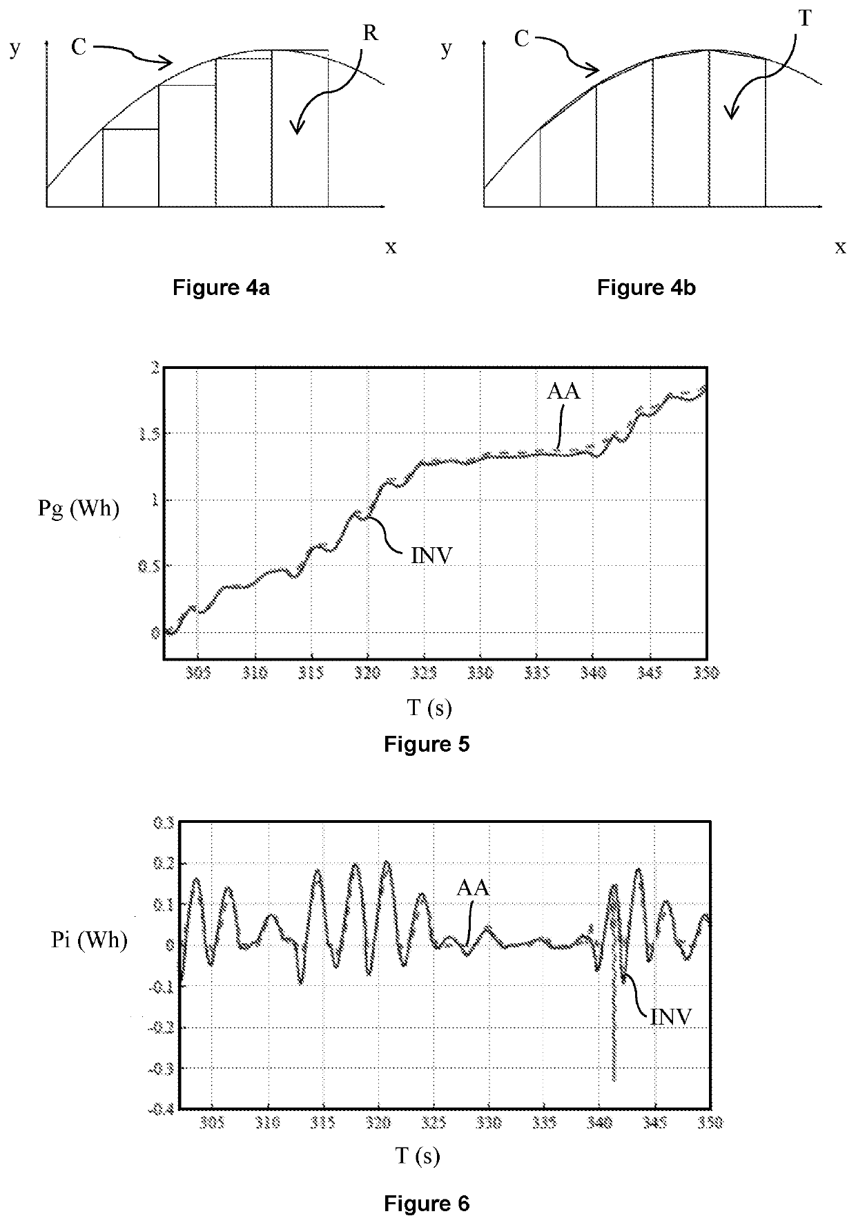
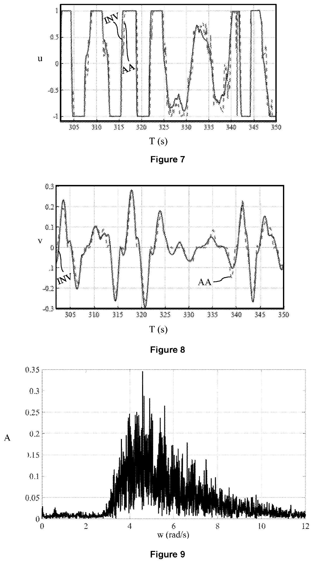
[0232]The control method according to the invention is compared with the control method described in French patent application FR-2,973,448 (WO-2012 / 131,186), by studying the responses obtained with these two methods. This comparative example was implemented on a wave energy system corresponding to the diagram of FIG. 3. FIGS. 5 to 8 are curves of the values obtained with the two methods. For this example, the spectral density of the waves being considered is in accordance with the curve in FIG. 9 of amplitude A as a function of frequency w (rad / s). In curves 5 to 8, the results obtained by the control method according to the invention are denoted by INV and ...


PUM


Abstract

The present invention provides improvement of the operation of a wave energy system by use of a method for predictive control (COM) of the converter machine that maximizes the energy generated by considering the energy conversion efficiency (MOD ENE) and a wave prediction (PRED). Furthermore, the method according to the invention determines the optimal control by minimizing an objective function weighted and discretized by the trapezoidal rule.

Description

CROSS REFERENCE TO RELATED APPLICATIONS[0001]Reference is made to PCT / EP2017 / 077410 filed Oct. 26, 2017, and French Application No. 16 / 60.872 filed Nov. 9, 2016, which are incorporated herein by reference in their entirety.BACKGROUND OF THE INVENTIONField of the Invention[0002]The invention relates to devices for converting wave energy to electrical or hydraulic energy.Description of the Prior Art[0003]Renewable energy resources have generated strong interest for years. They are clean, free and inexhaustible, which are major assets in a world facing the inexorable depletion of the available fossil resources and recognizing the need to preserve the planet. Among these resources, wave energy, a source relatively unknown amidst those widely publicized, such as wind or solar energy, contributes to the vital diversification of the exploitation of renewable energy sources. The devices, commonly referred to as “wave energy devices”, are particularly interesting because they allow electrici...

Claims


Application Information

Patent Timeline
Patent Type & Authority Patents(United States)
IPC IPC(8): F03B13/18F03B15/02F03B13/16F03B15/00
CPCF03B13/187F03B13/16F03B15/00F03B15/02F05B2240/40F05B2260/821F05B2260/84F05B2270/1033F05B2270/20F05B2270/30Y02E10/30
Inventor TONA, PAOLINONGUYEN, HOAI-NAM
Owner INST FR DU PETROLE
Why Eureka
Try Eureka