Method for erecting a concrete structure and climbing formwork

a concrete structure and climbing technology, applied in the field of concrete structure erection, can solve the problems of cumbersome attachment of temporary supports to the sub-frames supporting the main frame, and achieve the effect of improving the stability and stability of the structur

Active Publication Date: 2018-08-30
DOKA
View PDF0 Cites 4 Cited by
  • Summary
  • Abstract
  • Description
  • Claims
  • Application Information

AI Technical Summary

Benefits of technology

[0024]In another embodiment, the first support bracket is releasably attached to the support column in a first support position for being supported on the first floor slab adjacent to the first through-hole while the support column is transferred from the retracted position to the extended position and wherein the first support bracket is released from the support column and then releasably attached to the support column in a first transport position for being passed through the second through-hole while the support column is transferred from the extended position to the retracted position. In this embodiment, the first support bracket may be manually repositioned from the first support position, which is arranged for transferring vertical loads into the respective floor slab, to the first transport position, which is arranged for allowing passage of the first support bracket through the through-hole in the respective floor slab. The advantage of this embodiment is that the first support bracket need not be carried to the next floor when the climbing formwork is repositioned. In the first transport position, the first support bracket is transported upwards together with the support column. In other words, the support column may be used as an elevator for transporting the first support bracket during a climbing step of the climbing formwork.
[0025]In one embodiment, the first support bracket in the first support position and / or in the first transport position is releasably attached to a bearing, the bearing being connected to a lower end of the jack. The support column may comprise a mast with an upper end carrying the frame which may have a number of sub-frames, for example cross-beams from which the formworks are suspended. The jack is operably connected to the mast for extending or retracting the support column (i.e. for increasing or decreasing the distance between the upper end of the mast and the bearing on the lower end of the support column). In one example, a vertical extension of the first support bracket is less than the vertical extension of the bearing. In this way, an optimal load transfer from the bearing at the lower end of the support column via the first support bracket, arranged in the first support position, to the first floor slab is achieved.

Problems solved by technology

It is a drawback of this prior art that temporary supports, namely said adjustable struts, are required for supporting the main frame while repositioning the screw jacks.
Furthermore, the attachment of the temporary supports on the sub-frames supporting the main frame is cumbersome.

Method used


Image

  • Method for erecting a concrete structure and climbing formwork
  • Method for erecting a concrete structure and climbing formwork
  • Method for erecting a concrete structure and climbing formwork

Examples


Embodiment Construction

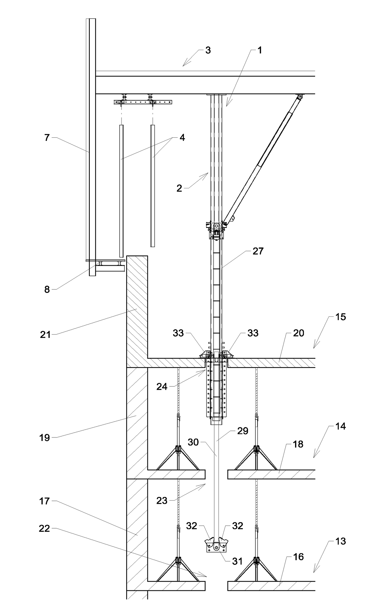
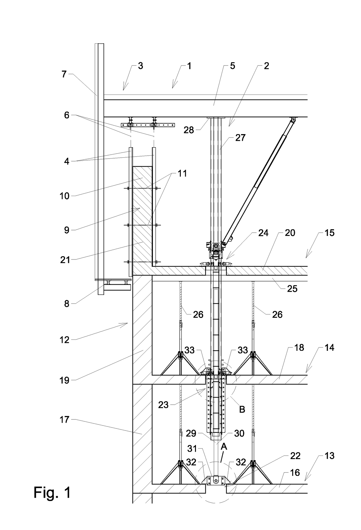
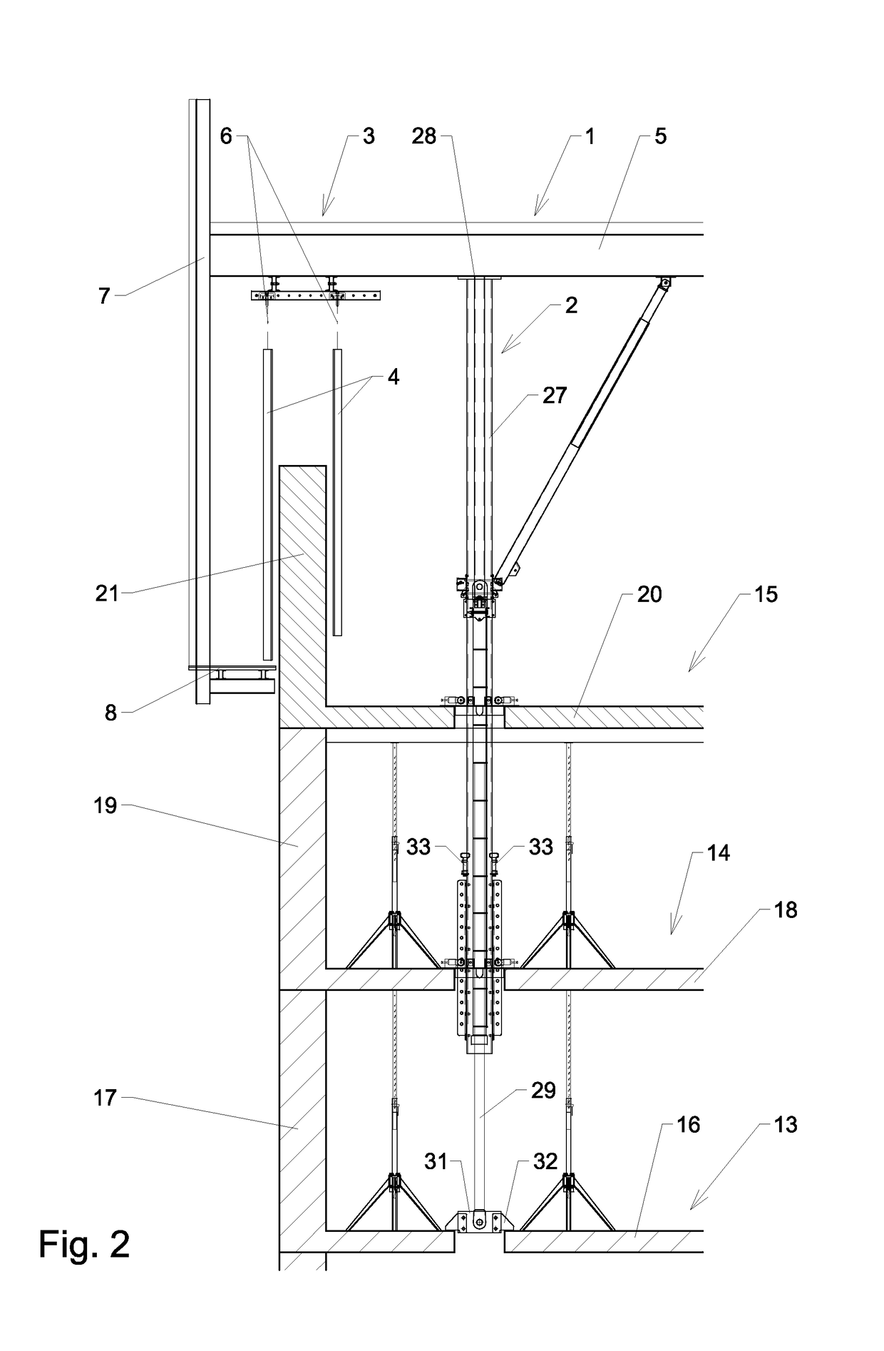
[0071]Referring to FIGS. 1 to 5 of the drawings, a first embodiment of the disclosure relates to a climbing formwork 1 with a (generally vertically extending) support column 2, a frame 3 and formworks 4. In the shown embodiment, frame 3 has a cross-beam 5 from which the formworks (for example sheathings) 4 are suspended (as illustrated by lines 6 in FIG. 1 and FIG. 2). In this embodiment, a single leg support column 2 is used. Thus, the support column 2 is not rigidly connected to another support column 2 by means other than the frame 3. It is apparent that frame 3 may comprise a number of other known frame components, such as a vertical frame member 7 carrying a working platform 8. As is well known in the prior art, the formworks 4 delimit a cavity 9 for receiving concrete 10 therebetween. Furthermore, anchors 11 may be arranged for holding the formworks 4 together during casting. In the shown example, the climbing formwork 1 is used for constructing a concrete structure 12, for ex...


PUM


Abstract

A method for erecting a concrete structure by successively casting at least a first casting segment with a first floor slab, a second casting segment with a second floor slab and a third casting segment with a third floor slab includes providing a support column carrying a frame for suspending a formwork therefrom, the support column having a jack for transferring the support column from a retracted position to an extended position and vice versa, supporting the support column, by means of a first support bracket, arranging a second support bracket, at a vertical position between the second and third floor slab, on the support column, activating the jack for transferring the support column from the retracted position to the extended position, supporting the support column, by means of the second support bracket, and activating the jack for transferring the support column from the extended position to the retracted position.

Description

TECHNICAL FIELD[0001]The present disclosure relates generally to the erection of concrete structures, such as high-rise buildings, utilizing climbing formworks.DESCRIPTION OF THE RELATED ART[0002]In the prior art, a great variety of formworks has been proposed. Such formworks, also known as shuttering, are temporary retaining structures for defining and supporting a volume to be filled with concrete. As is well known in the prior art, climbing formworks are used for transferring the loads resulting from the present casting step into previously formed casting segments. In this way, concrete-structures such as high-rise buildings can be erected without the need for scaffolding extending the full height of the construction. Such climbing formworks are successively raised and secured to the concrete structure, which procedure is repeated after each casting step.[0003]A climbing formwork was proposed, for example, in U.S. Pat. No. 5,263,835. In this prior art, a building construction sys...

Claims


Application Information

Patent Timeline
Patent Type & Authority Applications(United States)
IPC IPC(8): E04G11/30
CPCE04G11/24E04G11/28E04B1/161E04B1/35E04G17/002E04G19/003
Inventor GRUEBLER, STEFAN
Owner DOKA
Why Eureka
Try Eureka