
Regenerative cooling system

Active Publication Date: 2018-08-30
RABHI VIANNEY
View PDF0 Cites 1 Cited by
  • Summary
  • Abstract
  • Description
  • Claims
  • Application Information

AI Technical Summary

Benefits of technology

The invention is a new sealing device that allows the expander cylinder to operate at high temperature, resulting in a higher efficiency of the transfer-expansion and regeneration heat engine. The device prevents heat from migrating from hot parts to cold parts, while allowing the heat to escape as a pure loss through the colder walls of the cylinder. This ensures an elevated efficiency of the heat engine. It is also important to reduce the temperature of the internal walls of the expander cylinder to ensure the optimal efficiency of the heat engine, while using materials of lower sale price.

Problems solved by technology

However, it remains less than that of slow two-stroke Diesel engines with very large displacement, which are found for example in naval propulsion or the stationary production of electricity.
Moreover, their response time in power modulation is long.
For these various reasons, their area of application is limited and they are hard to adapt to land transportation and especially to cars and trucks.
These materials are hard and difficult to machine.
Consequently, the sale price of finished parts is relatively elevated, which is an impediment to the adoption by the automotive industry of the transfer-expansion and regeneration heat engine described in the patent application FR 15 51593.
In fact, these two actions would have the harmful consequence of significantly reducing the final efficiency of the transfer-expansion and regeneration heat engine.
In the current state of the art, therefore, one needs to choose between a transfer-expansion and regeneration heat engine with very high efficiency, yet costly and hard to produce, and an engine based on the same principle but resorting to materials less costly to produce, but at the price of a large decrease in efficiency.
This constitutes a dilemma.

Method used


Image

  • Regenerative cooling system
  • Regenerative cooling system

Examples


Embodiment Construction

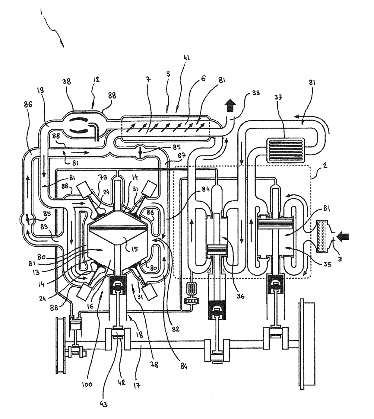
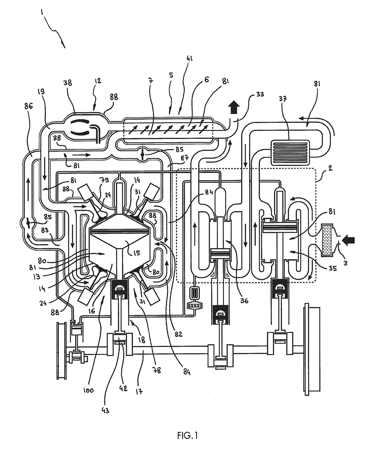
[0046]There is shown in FIG. 1 the regenerative cooling system 100, various details of its components, its variants, and its accessories.

[0047]As is shown in FIG. 1, the regenerative cooling system 100 is provided for a regenerative heat engine 1, the latter comprising at least one regenerative heat exchanger 5 having a high-pressure regeneration duct 6 in which a working gas 81 circulates, becoming heated there, and having been previously compressed by a compressor 2.

[0048]Upon leaving the high-pressure regeneration duct 6, said gas 81 is superheated by a heat source 12 before being introduced into a gas expander 78, in which it is expanded to produce work on a power takeoff shaft 17.

[0049]The working gas 81 is then expelled from the gas expander 78 and introduced into a low-pressure regeneration duct 7 of the regenerative heat exchanger 5, said gas 81—by circulating in said duct 7—surrendering a large measure of its residual heat to the working gas 81 circulating in the high-press...


PUM


Abstract

The regenerative cooling system (100) is provided for a regenerative heat engine (1) and comprises a cooling chamber (79) which surrounds a gas expander (78), leaving open a gas circulation space (80) between said chamber (79) and said expander (78), a working gas (81) expelled from the gas expander (78) circulating in said space (80) before returning to a regenerative heat exchanger (5) where it is cooled, a large portion of the heat of said gas (81) being reintroduced into the thermodynamic cycle of the regenerative heat engine (1).

Description

[0001]The present invention relates to a regenerative cooling system which constitutes, among other things, an improvement of the transfer-expansion and regeneration heat engine which was the subject matter of patent application No. FR 15 51593 of 25 Feb. 2015 belonging to the applicant, and the patent published on 1 Sep. 2016 as No. US 2016 / 0252048 A1, likewise belonging to the applicant.[0002]The Brayton regeneration cycle, ordinarily implemented by means of centrifugal compressors and turbines, is familiar.[0003]According to this mode of embodiment, the cycle results in engines which provide a significantly higher efficiency that that of controlled-ignition engines. The efficiency is comparable to that of fast Diesel engines. However, it remains less than that of slow two-stroke Diesel engines with very large displacement, which are found for example in naval propulsion or the stationary production of electricity.[0004]Besides a very modest overall efficiency, the engines with ce...

Claims


Application Information

Patent Timeline
IPC IPC(8): F02G1/055F02G3/02F02G1/057
CPCF02G1/055F02G3/02F02G1/057F02G2250/03F02G2254/10F02G2254/20
Inventor RABHI, VIANNEY
Owner RABHI VIANNEY
Learn More