Method for manufacturing liquid crystal display panel

a technology of liquid crystal display panel and liquid crystal, which is applied in the direction of instruments, non-linear optics, optics, etc., can solve the problems of vacuum bubbles and poor liquid crystal dispersion, and achieve the effects of poor liquid crystal dispersion, and reducing the use area of the circuit region

Inactive Publication Date: 2018-08-30
HKC CORP LTD +1
View PDF6 Cites 1 Cited by
  • Summary
  • Abstract
  • Description
  • Claims
  • Application Information

AI Technical Summary

Benefits of technology

[0029]The beneficial effects of this application are as follows: Because of a manufacturing process of the color filter layer, the flat layer is flush with the color filter layer, and the flat layer is connected to the color filter layer to form a same plane. Therefore, this can resolve the problem of vacuum bubbles on an edge caused because a large mismatch between the display region and the edge region leads to poor liquid crystal dispersion during cell formation, and reduce a use area of a circuit region on the bezel region, so that the substrates become smaller.
[0030]Further, the beneficial effects of this application are as follows: The color filter layer and the flat layer use a same material. Therefore, costs can be effectively reduced, and a success rate after cell formation can be improved.

Problems solved by technology

In a screen process of current COT technologies, a mismatch between a display region and an edge region thereof may be easily caused due to a topographical difference, leading to poor liquid crystal dispersion.
Consequently, the problem of vacuum bubbles occurs on the edge during a cell formation process.

Method used


Image

  • Method for manufacturing liquid crystal display panel
  • Method for manufacturing liquid crystal display panel
  • Method for manufacturing liquid crystal display panel

Examples


Embodiment Construction

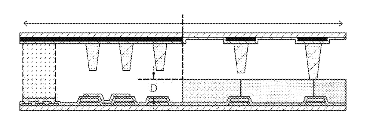
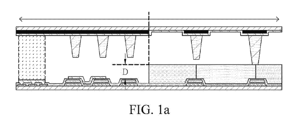
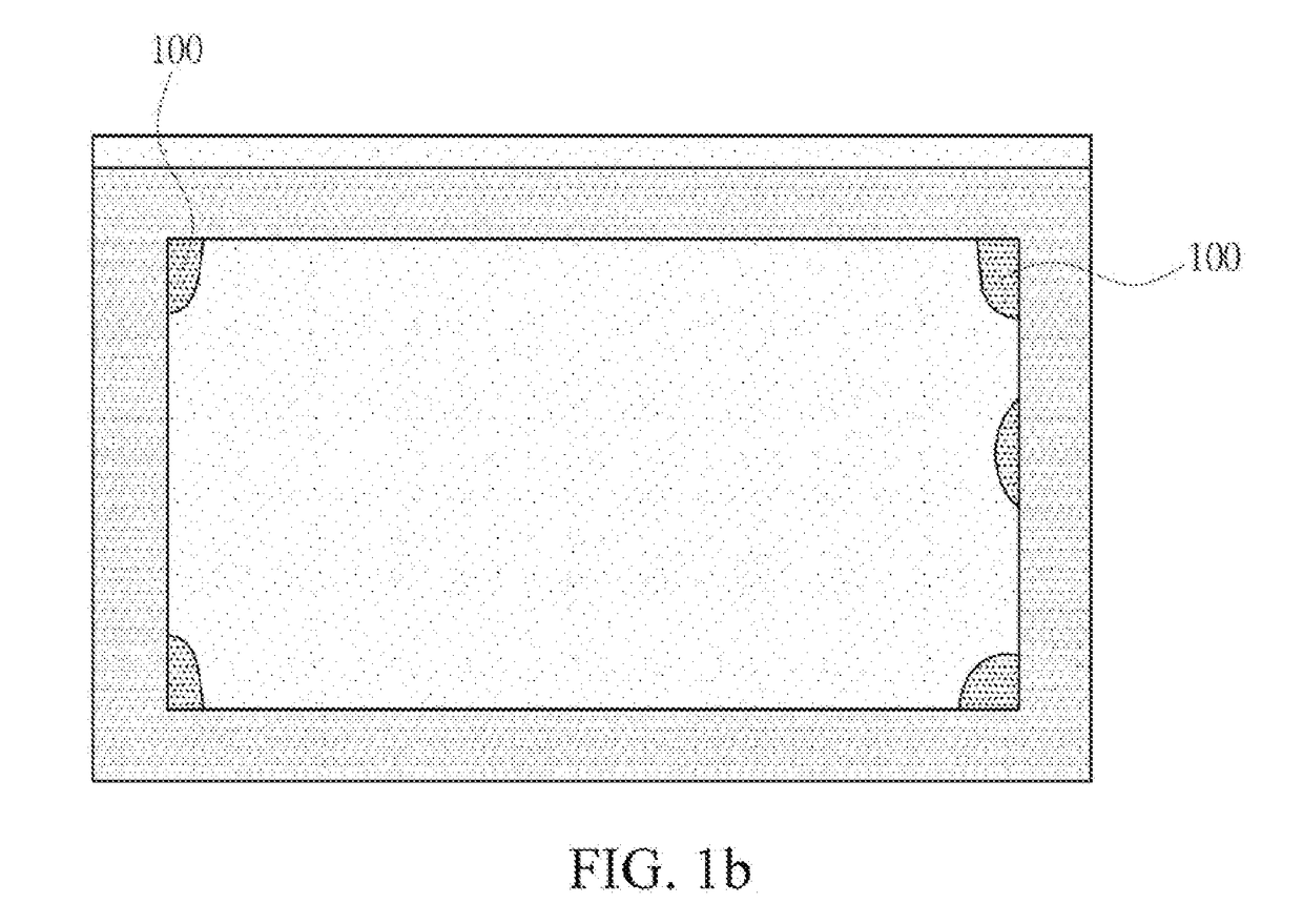
[0041]The following embodiments are described with reference to the accompanying drawings, used to exemplify specific embodiments for implementation of this application. Terms about directions mentioned in this application, such as “above”, “below”, “front”, “back”, “left”, “right”, “inside”, “outside”, and “side surface” merely refer to directions with reference to the accompanying drawings. Therefore, the used terms about directions are used to describe and understand this application, and are not intended to limit this application.

[0042]The accompanying drawings and the description are considered to be essentially exemplary, rather than limitative. In the figures, units with similar structures are represented by using the same reference number. In addition, for understanding and ease of description, the size and the thickness of each component shown in the accompanying drawings are arbitrarily shown, but this application is not limited thereto.

[0043]In the accompanying drawings, ...


PUM

PropertyMeasurementUnit
thicknessaaaaaaaaaa
lengthaaaaaaaaaa
dispersionaaaaaaaaaa

Abstract

This application relates to a method for manufacturing a liquid crystal display panel, including: providing a first substrate; providing a second substrate including a display region and a bezel region, where the bezel region is located on an edge of the second substrate and surrounds the display region; forming a color filter layer on the display region of the second substrate, where the color filter layer has a first thickness; forming a flat layer on the bezel region of the second substrate, where the flat layer surrounds the color filter layer, the flat layer has a second thickness, and the second thickness is the same as the first thickness, so that the flat layer is flush with the color filter layer, and the flat layer is connected to the color filter layer to form a same plane.

Description

BACKGROUNDTechnical Field[0001]This application relates to a method for manufacturing a liquid crystal display panel, and in particular, to a method for manufacturing a color filter on TFT (COT)-type liquid crystal display panel.Related Art[0002]Recently, a COT-type liquid crystal display using a thin film transistor (TFT) a color filter formed on a first substrate and a color filter is used due to the advantage that in the COT-type liquid crystal display, alignment margins of the first substrate and a second substrate are minimized to increase the aperture ratio.[0003]In a screen process of current COT technologies, a mismatch between a display region and an edge region thereof may be easily caused due to a topographical difference, leading to poor liquid crystal dispersion. Consequently, the problem of vacuum bubbles occurs on the edge during a cell formation process. Therefore, to overcome vacuum bubbles on the edge is a subject on which great efforts are always made in the COT p...

Claims


Application Information

Patent Timeline
Patent Type & Authority Applications(United States)
IPC IPC(8): G02F1/1335G02F1/1333
CPCG02F1/133514G02F1/133512G02F1/133308G02F1/1333G02F1/133357G02F1/1362G02F2201/40G02F1/133354G02F1/133388G02F1/13396G02F1/136222
Inventor CHEN, YU-JEN
Owner HKC CORP LTD
Why Eureka
Try Eureka