Check patentability & draft patents in minutes with Patsnap Eureka AI!

Electrostatic chuck table using method

Active Publication Date: 2018-08-30
DISCO CORP
View PDF4 Cites 1 Cited by
  • Summary
  • Abstract
  • Description
  • Claims
  • Application Information

AI Technical Summary

Benefits of technology

The present invention provides an electrostatic chuck table using method that can overcome limitations in processing workpieces. This method helps to suppress any limitations in processing the workpiece.

Problems solved by technology

Thus, there is a limit in processing the workpiece by using this laser processing apparatus.

Method used


Image

  • Electrostatic chuck table using method
  • Electrostatic chuck table using method
  • Electrostatic chuck table using method

Examples


Embodiment Construction

[0022]A preferred embodiment of the present invention will now be described in detail with reference to the drawings. The present invention is not limited to this preferred embodiment. Further, the components used in this preferred embodiment may include those that can be easily assumed by persons skilled in the art or substantially the same elements as those known in the art. Further, the configurations described below may be suitably combined. Further, the configurations may be variously omitted, replaced, or changed without departing from the scope of the present invention.

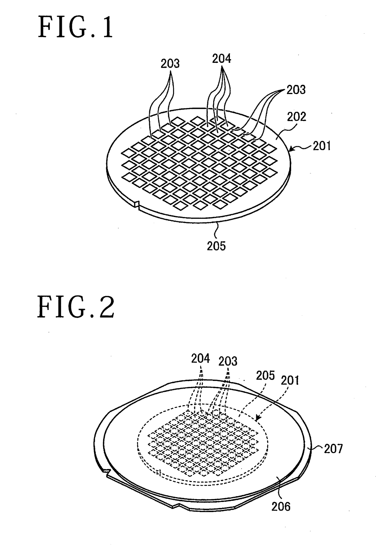
[0023]There will now be described an electrostatic chuck table using method according to a preferred embodiment of the present invention with reference to the drawings. FIG. 1 is a perspective view of a workpiece 201 to be held on an electrostatic chuck table in the electrostatic chuck table using method according to this preferred embodiment. FIG. 2 is a perspective view showing a condition that the workpiece ...


PUM

PropertyMeasurementUnit
Wavelengthaaaaaaaaaa
Electric potential / voltageaaaaaaaaaa
Wavelengthaaaaaaaaaa

Abstract

An electrostatic chuck table includes a plate-shaped base portion capable of transmitting a laser beam to be applied to a workpiece and an electrostatic attraction electrode portion capable of transmitting the laser beam. The laser beam has a transmission wavelength to the workpiece. The base portion has a first surface and a second surface opposite to the first surface. The electrode portion is formed on the first surface of the base portion. A method for using the electrostatic chuck table includes a workpiece holding step of applying a voltage to the electrode portion formed on the first surface to thereby electrostatically hold the workpiece on the second surface, and a modified layer forming step of applying the laser beam through the first surface to a predetermined position inside the workpiece held on the second surface to thereby form a modified layer inside the workpiece.

Description

BACKGROUND OF THE INVENTIONField of the Invention[0001]The present invention relates to a using method for an electrostatic chuck table capable of transmitting a laser beam.Description of the Related Art[0002]Conventionally known is a processing method using a laser processing apparatus for forming a modified layer inside a wafer having semiconductor devices or optical devices such as LEDs (light emitting diodes) and then dividing the wafer along the modified layer as a break start point (see Japanese Patent No. 3408805, for example).[0003]As compared with a dicing method using a cutting blade for cutting a wafer as supplying a cutting water to the cutting blade, the above processing method described in Japanese Patent No. 3408805 is very useful for a wafer having narrower streets because the kerf width (kerf loss) along each street can be made very small. Further, in this processing method, a mechanical shock to the workpiece can be greatly reduced, so that this processing method i...

Claims


Application Information

Patent Timeline
IPC IPC(8): H01L21/683B81C99/00B23K26/53
CPCH01L21/6833B81C99/001B23K26/53H01L21/78B23K26/009B23K26/037B23K2103/56H01L21/76H01L21/6831B23K26/38
Inventor FURUTA, KENJISATO, YURIKOMATSUZAKI, SAKAE
Owner DISCO CORP
Features
  • R&D
  • Intellectual Property
  • Life Sciences
  • Materials
  • Tech Scout
  • Unparalleled Data Quality
  • Higher Quality Content
  • 60% Fewer Hallucinations
Learn More