
Organic Light Emitting Device

a light-emitting device and organic technology, applied in semiconductor devices, diodes, electrical devices, etc., can solve problems such as the light extraction efficiency of organic light-emitting devices, and achieve the effect of improving the outward light-emitting efficiency and reducing power consumption

Active Publication Date: 2018-08-30
LG DISPLAY CO LTD
View PDF2 Cites 21 Cited by
  • Summary
  • Abstract
  • Description
  • Claims
  • Application Information

AI Technical Summary

Benefits of technology

The patent describes an organic light emitting device that improves its efficiency and reduces power consumption. This is achieved by using an overcoat layer with convex or concave parts, with the concave parts having a smaller FWHM than the convex parts. The device also includes a first electrode, an organic light emitting layer, and a second electrode. Overall, this patent provides an effective solution for improving the device's performance.

Problems solved by technology

Therefore, the light extraction efficiency of the organic light emitting device becomes an issue.

Method used


Image

  • Organic Light Emitting Device
  • Organic Light Emitting Device
  • Organic Light Emitting Device

Examples


Embodiment Construction

[0026]Hereinafter, some embodiments of the present invention will be described in detail with reference to the accompanying illustrative drawings. In designating elements of the drawings by reference numerals, the same elements will be designated by the same reference numerals although they are shown in different drawings. Further, in the following description of the present invention, a detailed description of known functions and configurations incorporated herein will be omitted when it may make the subject matter of the present invention rather unclear.

[0027]In addition, terms, such as first, second, A, B, (a), (b) or the like may be used herein when describing components of the present invention. Each of these terminologies is not used to define an essence, order or sequence of a corresponding component but used merely to distinguish the corresponding component from other component(s). In the case that it is described that a certain structural element “is connected to”, “is coup...


PUM


Abstract

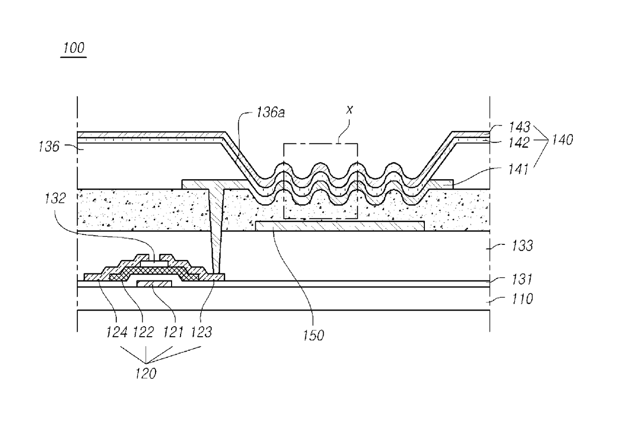
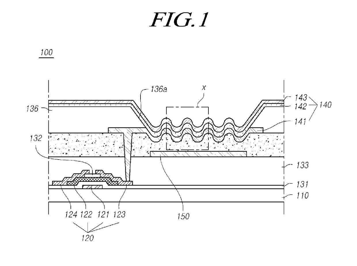
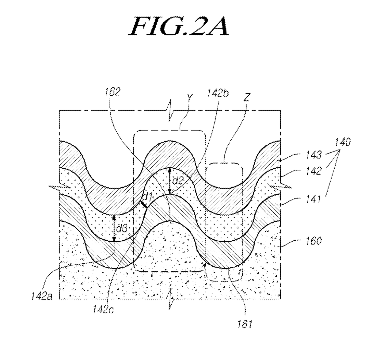
Provided is an organic light emitting device including an overcoat layer on a substrate, a first electrode disposed on the overcoat layer, an organic light emitting layer disposed on the first electrode and including a convex or concave curve; and a second electrode disposed on the organic light emitting layer.

Description

BACKGROUND1. Field[0001]The disclosure relates to an organic light emitting device.2. Description of the Related Art[0002]An organic light emitting device, has advantages in that, by using a self-light emitting organic light emitting element, a response speed is high, a contrast ratio is high, a light emitting efficiency is high, and a viewing angle is wide.[0003]Light emitted from an organic light emitting layer of the organic light emitting device passes through several components of the organic light emitting device to exit from the organic light emitting device. However, some light emitted from the organic light emitting layer does not exit the organic light emitting device, but is locked in the organic light emitting device. Therefore, the light extraction efficiency of the organic light emitting device becomes an issue. A method of attaching a Micro Lens Array (MLA) to the outside of a substrate of the organic light emitting device has been used in order to improve the light e...

Claims


Application Information

Patent Timeline
Patent Type & Authority Applications(United States)
IPC IPC(8): H01L27/32H01L51/52
CPCH01L27/326H01L51/5203H01L27/3276H01L27/322H01L51/5262H10K59/38H10K59/124H10K59/80515H10K50/813H10K50/86
Inventor JANG, JIHYANGKIM, SOOKANGJO, SOYOUNGKOO, WONHOELIM, HYUNSOO
Owner LG DISPLAY CO LTD
Learn More