
Spark plug

Inactive Publication Date: 2018-08-30
NGK SPARK PLUG CO LTD
View PDF1 Cites 0 Cited by
  • Summary
  • Abstract
  • Description
  • Claims
  • Application Information

AI Technical Summary

Benefits of technology

The present invention provides a spark plug that has improved anti-warping and anti-peeling performance of the discharge tip. This is achieved by the design of the discharge tip, which includes a discharge layer containing a noble metal or noble metal alloy and an intermediate layer containing a noble metal element. The inclusion of a melted portion in the electrode base material ensures a sufficient length of the melted portion, which reduces warping of the discharge tip. Additionally, the end surface of the intermediate layer may be exposed on the second-end side of the electrode base material, which further improves the anti-spark consumability of the discharge tip. The area of the surface of the discharge tip facing the center electrode may also be increased to increase the durability of the spark plug. Finally, the proportion of the noble metal element in the discharge layer and intermediate layer may be greater than or equal to 100% to further reduce warping of the discharge tip.

Problems solved by technology

However, since the linear expansion coefficients differ, such a composite tip may be warped with respect to the electrode.

Method used


Image

  • Spark plug
  • Spark plug
  • Spark plug

Examples


first embodiment

A. First Embodiment

A1. Structure of a Spark Plug:

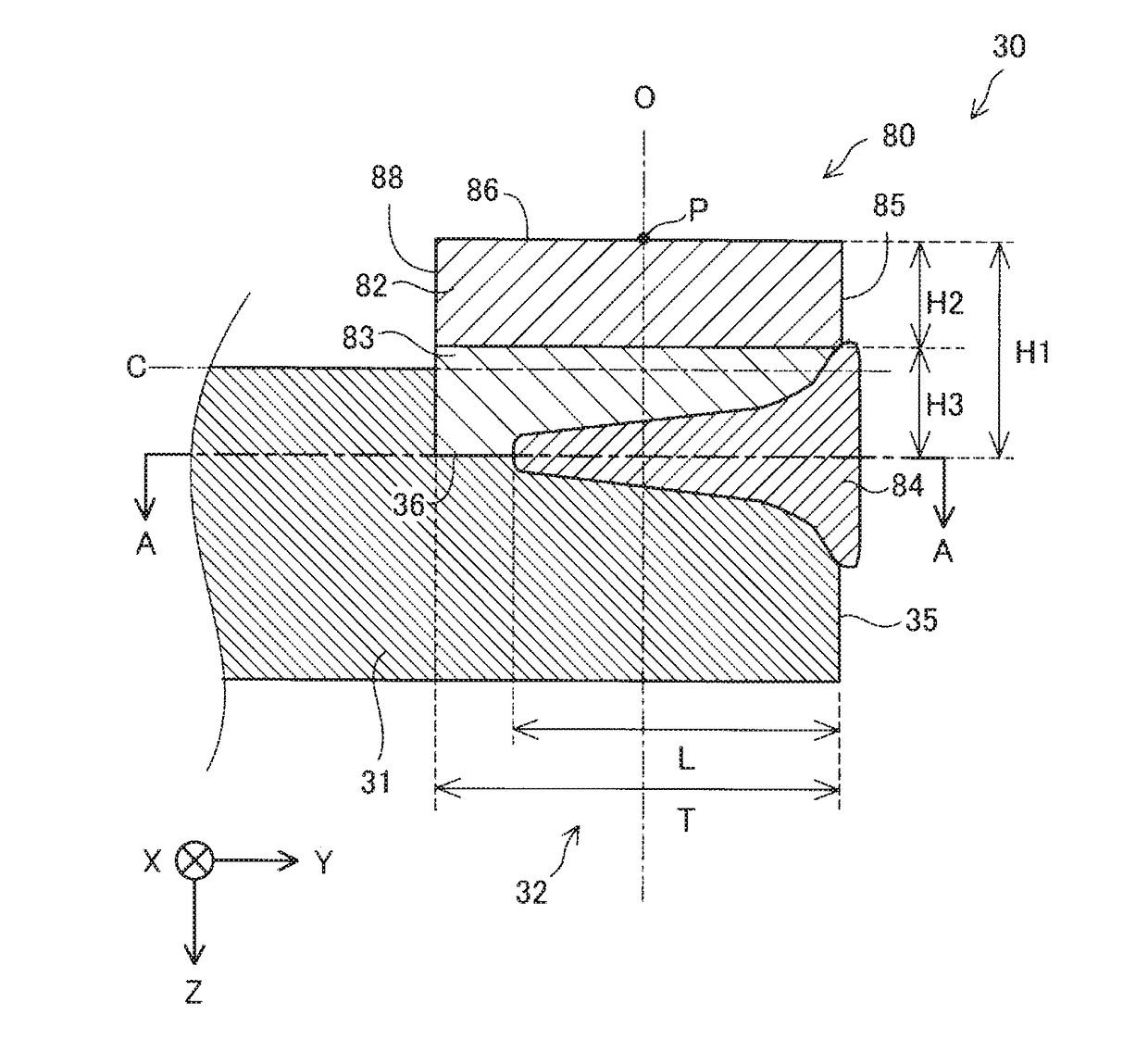
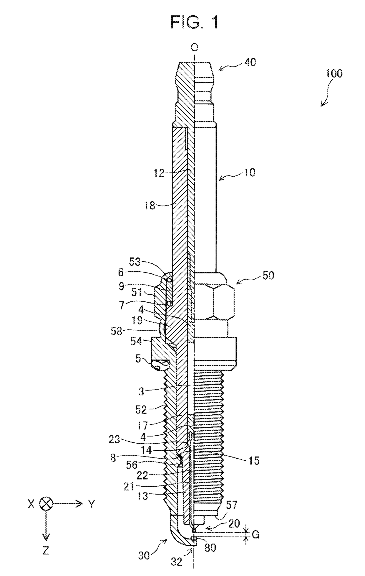
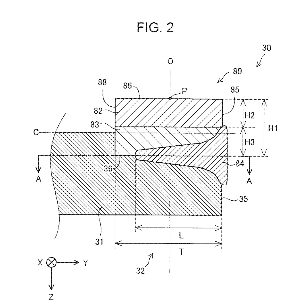
[0023]FIG. 1 is a partial sectional view of a spark plug 100 according to an embodiment of the present invention. The spark plug 100 has an elongated shape along an axial line O. In FIG. 1, the right side of the axial line O indicated by an alternate long and short dash line corresponds to an external front view, and the left side of the axial line O corresponds to a sectional view in which the axial line O extends. In the description below, the lower side in FIG. 1 is called a front end side of the spark plug 100, and the upper side in FIG. 1 is called a back end side. An X axis, a Y axis and a Z axis in FIG. 1 corresponds to an X axis, a Y axis, and a Z axis in each of the other figures. The axial line O is parallel to the Z axis. In FIG. 1, the front end side of the spark plug 100 corresponds to a +Z direction, and the back end side of the spark plug 100 corresponds to a −Z direction. The term “Z direction” refers to directions par...

second embodiment

B. B1. Structure of a Spark Plug

[0056]FIG. 7 is a longitudinal sectional view of a front end portion 32a of a ground electrode 30a of a spark plug according to a second embodiment. The longitudinal sectional view shown in FIG. 7 is parallel to an axial line O and includes a center line C of the ground electrode 30a. In the ground electrode 30a according to the embodiment, an end surface 87a of an intermediate layer 83a of a discharge tip 80a is exposed at a second-end-35a side of an electrode base material 31a. Even in the spark plug according to this embodiment, as in the spark plug according to the first embodiment, when the discharge tip 80a is viewed from the −Z direction, a melted portion 84a is formed in at least a region on the second-end-35a side of the electrode base material 31a from a center P of the discharge tip 80a (discharge layer 82a), and a proportion D of a depth L of the melted portion 84a is greater than or equal to 76.2%. The other structural features of the sp...

first modification

C. Modifications: C1. First Modification

[0061]In the above-described various embodiments, the discharge tip 80 includes one discharge layer 82 and one intermediate layer 83, and the discharge tip 80a includes one discharge layer 82a and one intermediate layer 83a. In contrast, a discharge tip 80c may include two or more intermediate layers.

[0062]FIG. 8 is a longitudinal sectional view of a front end portion 32c of a ground electrode 30c. In the ground electrode 30c shown in FIG. 8, the discharge tip 80c includes a discharge layer 82c, a first intermediate layer 83b, and a second intermediate layer 83c. The first intermediate layer 83b contains a noble metal element (such as Pt) that is contained by the largest amount in the discharge layer 82c, and an element (such as Ni) that is contained in an electrode base material 31c. The second intermediate layer 83c contains the noble metal element (such as Pt) that is contained by the largest amount in the discharge layer 82c by an amount t...


PUM


Abstract

A spark plug wherein when a discharge tip is viewed from a direction of an axial line, a melted portion is formed in at least a region on a second-end side of an electrode base material from a center of a discharge layer, and wherein in a section that includes a center line along a longitudinal direction of a ground electrode and that is parallel to an axial line, a proportion of a length of the melted portion along the longitudinal direction to a length of the discharge tip along the longitudinal direction of the electrode base material is greater than or equal to 76.2%, with the length of the melted portion along the longitudinal direction being within a range in which the discharge tip exists along the longitudinal direction

Description

FILED OF THE INVENTION[0001]The present invention relates to a spark plug.BACKGROUND OF THE INVENTION[0002]Hitherto, a spark plug including a composite tip that includes two types of metals having different linear expansion coefficients and that is provided on an electrode has been known (see Japanese Unexamined Patent Application Publication No. H6-60959).[0003]However, since the linear expansion coefficients differ, such a composite tip may be warped with respect to the electrode. Therefore, in such a spark plug including a composite tip, there is a demand for a technology that is capable of reducing warping of the composite tip with respect to an electrode material.SUMMARY OF THE INVENTION[0004]The present invention is made to address the above-described problem, and can be realized in the following forms.[0005](1) According to a first aspect of the present invention, there is provided a spark plug comprising a center electrode that extends in a direction of an axial line, an ins...

Claims


Application Information

Patent Timeline
IPC IPC(8): H01T13/32H01T13/39
CPCH01T13/32H01T13/39H01T13/38H01T13/20H01T1/22H01T1/24
Inventor SUZUKI, KAORIKATO, TOMOAKI
Owner NGK SPARK PLUG CO LTD
Learn More