Fault current limiter

a current limiter and fault current technology, applied in the field of fault current limiters, can solve the problem of rapid limitation of peak current, and achieve the effect of compact structure, fast energy transfer and easy engineering

Active Publication Date: 2018-08-30
HUAZHONG UNIV OF SCI & TECH
View PDF2 Cites 3 Cited by
  • Summary
  • Abstract
  • Description
  • Claims
  • Application Information

AI Technical Summary

Benefits of technology

[0017]1. Compared with the fault current limiter in the prior art, the hybrid superconducting fault current limiter of the invention is capable of fast energy transfer, easy to engineer, has a compact structure, and exhibits outstanding performance index in cost, size, complexity, and response speed. Based on the characteristics of the resistive and the inductive superconducting fault current limiters, a topological structure of the hybrid superconducting fault current limiter including resistive components and inductive components is put forward to protect the DC system when the short-circuit fault occurs. In normal operation of the DC system, the fault current limiter works as a smoothing reactor, and has no energy consumption. When a fault develops, the fault current limiter can obviously limit the current and works to compensate the voltage drop of the DC system. Because the superconducting inductor of the current limiter is connected to a shunt resistor in parallel, when a fault occurs, the fault current is quickly diverted to the resistor branch, and the peak current is limited. When the direct current circuit breaker is switched off, the current limiting function of the current limiter can be further improved, and the steady short-circuit current is limited. The superconducting inductor is unlikely to quench during the current limiting process, thus ensuring the security and stability of the superconducting structure.
[0018]2. The hybrid superconducting fault current limiter based on fast energy transfer can be applied to DC low-voltage lines and DC high-voltage transmission lines, and can respond to monopolar grounding fault and bipolar short-circuit fault, thus the requirements for fault current limiter as an important device for power grid construction under the condition that the short-circuit capacity of the power grid are increasing are satisfied, and relay protection configuration and stability of the DC system are maintained, meanwhile, the transient stability and the security in the steady state of the power grid are ensured.
[0019]3. The hybrid superconducting fault current limiter of the invention is capable of fast energy transfer, easy to engineer, has a compact structure, and exhibits outstanding performance index in cost, size, complexity, and response speed.

Problems solved by technology

When a fault develops, the inductor prevents the current from increasing, and the fault current is diverted to a resistor branch where the current-limiting resistor quickly takes effect, thus the peak current is quickly limited.

Method used


Image

  • Fault current limiter
  • Fault current limiter
  • Fault current limiter

Examples


Embodiment Construction

[0029]For further illustrating the invention, experiments detailing a hybrid superconducting fault current limiter are described below. It should be noted that the following examples are intended to describe and not to limit the invention.

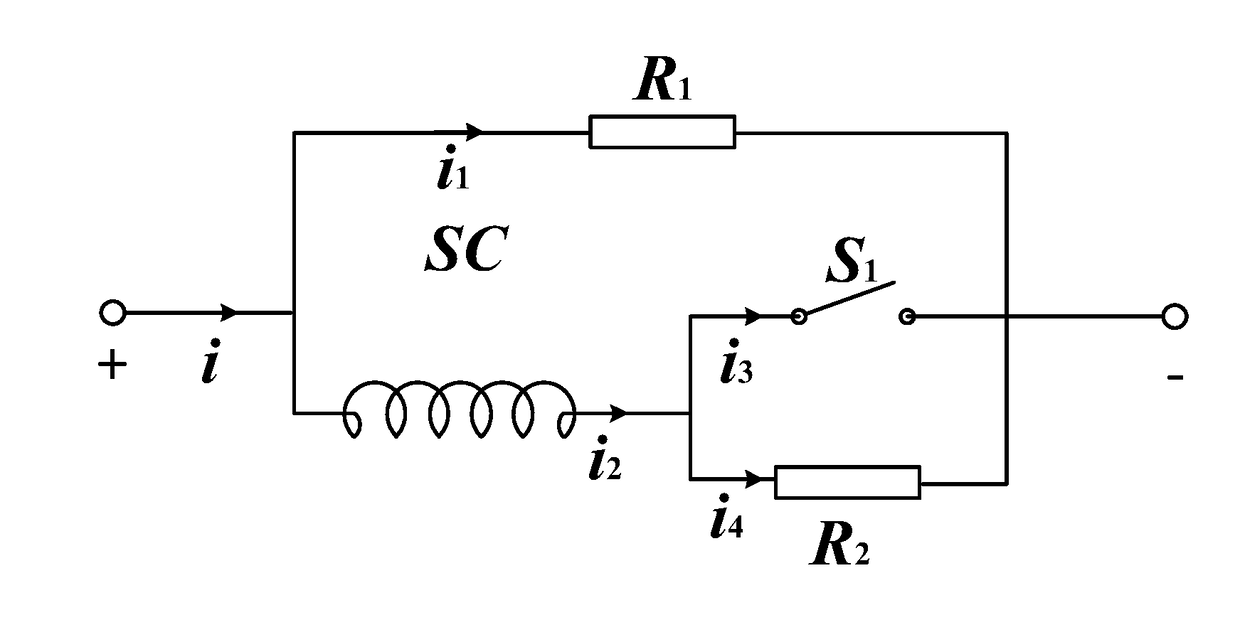
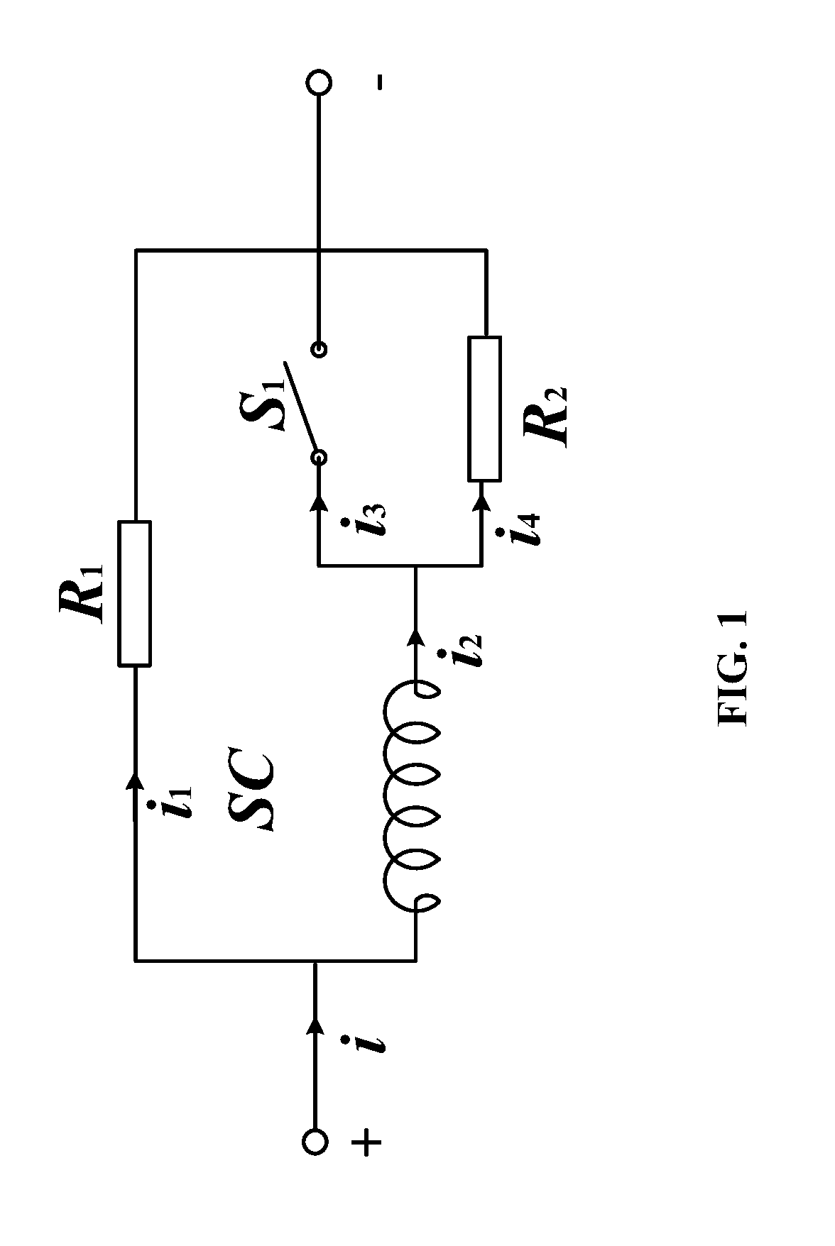
[0030]A hybrid superconducting fault current limiter comprises an inductor, a direct current circuit breaker, a shunt resistor, and a first fixed resistor. The inductor comprises wound superconducting wires. The direct current circuit breaker and the inductor are connected in series to form a series branch. The shunt resistor is connected in parallel to the series branch. The first fixed resistor is connected in parallel to the direct current circuit breaker.

[0031]In a class of this embodiment, the main structure of the fault current limiter comprises the inductor and the current-limiting resistor. The inductor and the current-limiting resistor are connected in parallel and form two branches on which the current flows. The inductor comprises wound ...


PUM

PropertyMeasurementUnit
peak currentaaaaaaaaaa
equivalent resistanceaaaaaaaaaa
resistive voltageaaaaaaaaaa

Abstract

A fault current limiter, including: an inductor, a direct current circuit breaker, a shunt resistor, and a first fixed resistor. The inductor includes wound superconducting wires. The direct current circuit breaker and the inductor are connected in series to form a series branch. The shunt resistor is connected in parallel to the series branch. The first fixed resistor is connected in parallel to the direct current circuit breaker.

Description

CROSS-REFERENCE TO RELATED APPLICATIONS[0001]Pursuant to 35 U.S.C. § 119 and the Paris Convention Treaty, this application claims the benefit of Chinese Patent Application No. 201720175479.1 filed Feb. 27, 2017, the contents of which are incorporated herein by reference. Inquiries from the public to applicants or assignees concerning this document or the related applications should be directed to: Matthias Scholl P. C., Attn.: Dr. Matthias Scholl Esq., 245 First Street, 18th Floor, and Cambridge, Mass. 02142.BACKGROUND OF THE INVENTIONField of the Invention[0002]The invention relates to a fault current limiter.Description of the Related Art[0003]High voltage direct current (DC) circuit breakers are considered to be one of the effective ways to solve the problem of short-circuit fault in DC power systems. However, with the rapid development of the power transmission network, the short-circuit current is increasingly large, and conventional high voltage DC circuit breakers are unable ...

Claims


Application Information

Patent Timeline
Patent Type & Authority Applications(United States)
IPC IPC(8): H02H9/02H01F37/00H01F27/24
CPCH02H9/023H01F27/24H01F37/005H01F6/00H01F38/023H01F2006/001Y02E40/60
Inventor REN, LILIANG, SIYUANTANG, YUEJINXU, YINGXIA, ZHONGWANG, ZUOSHUAISHI, JINGLI, JINGDONGZHANG, LIHUIYAN, SINIANYANG, ZHANGWEIZHANG, YI
Owner HUAZHONG UNIV OF SCI & TECH
Why Eureka
Try Eureka