
Driver circuit, corresponding ultrasound apparatus and method

a driver circuit and ultrasound technology, applied in the field of electronic driver circuits, can solve problems such as power dissipation, integration problems, occupation of the area,

Active Publication Date: 2018-08-30
STMICROELECTRONICS SRL
View PDF0 Cites 8 Cited by
  • Summary
  • Abstract
  • Description
  • Claims
  • Application Information

AI Technical Summary

Benefits of technology

The patent describes a circuit solution that combines the functions of linear and pulsed drivers using the same output power components. This results in several advantages, such as avoiding the complete switch-off of the stage during linear operation to prevent charge injection and reduce start-up time.

Problems solved by technology

A linear driver can also have certain drawbacks, such as the power dissipation, some integration issues, the occupation in area and, as a result, a high cost per channel.
This solution can offer advantages for example in terms of high-level integration, reduced power dissipated by the circuit, limited occupied area and low cost per channel, but also drawbacks in terms of flexibility or optimization of the excitation of the active element.

Method used


Image

  • Driver circuit, corresponding ultrasound apparatus and method
  • Driver circuit, corresponding ultrasound apparatus and method
  • Driver circuit, corresponding ultrasound apparatus and method

Examples


Embodiment Construction

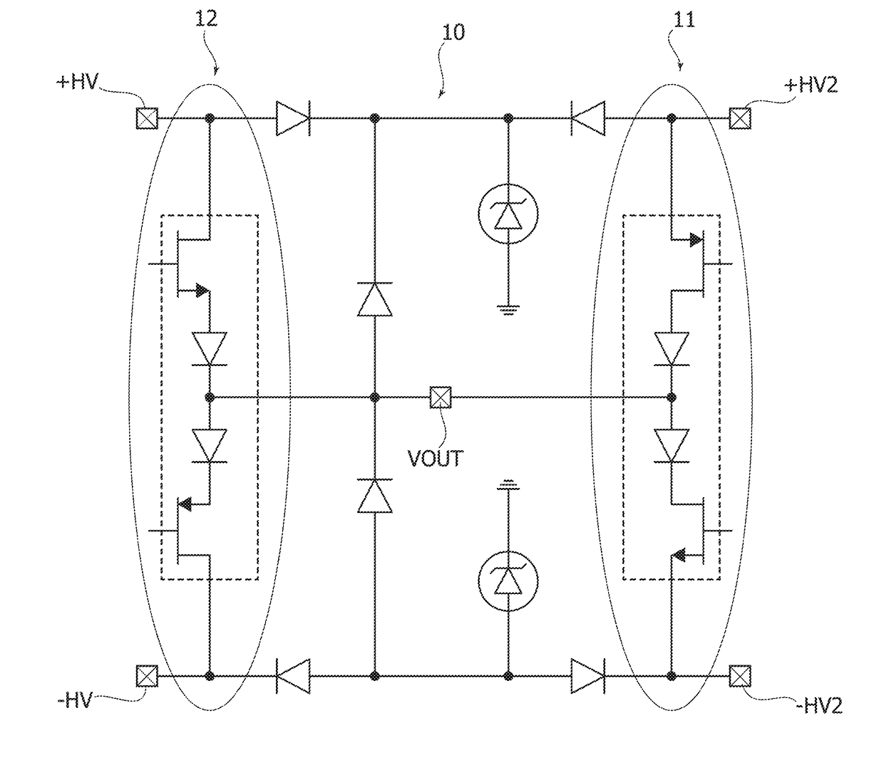
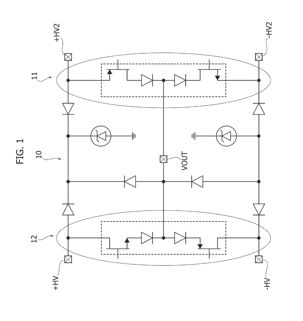
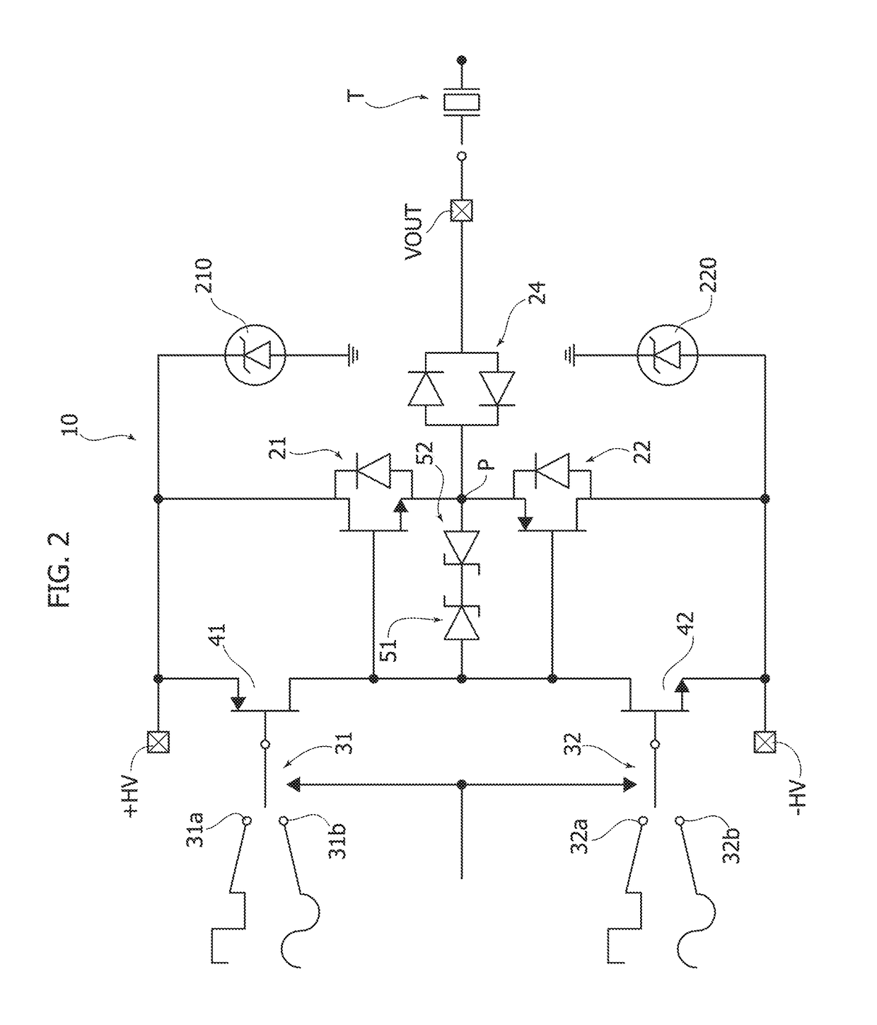
[0024]In the description that follows, various details are illustrated that are specific to the aim of providing a deeper understanding of various exemplary embodiments according to the description. The embodiments may be obtained without one or more of the specific details, or with other methods, components, materials, etc. In other cases, known structures, materials or operations are not illustrated or described in detail so that the various aspects of the embodiments will not be rendered unclear. A reference to “an embodiment” in the framework of the present description is intended to indicate that a particular configuration, structure or feature described in relation to the embodiment is included in at least one embodiment. Accordingly, the phrases such as “in one embodiment,” which may appear at various points of the present description, do not necessarily make reference to exactly the same embodiment. Furthermore, particular configurations, structures or features may be combin...


PUM


Abstract

A driver circuit for driving, for example, ultrasonic transducers in medical equipment, such as ultrasound scanning equipment. The driver circuit includes first inputs receptive of a pulsed signal, second inputs receptive of an analog signal, an output for applying a pulsed drive signal or an analog drive signal to a load. A pair of output transistors of complementary polarities are positioned with their current paths in series between opposing supply lines with a connection point intermediate between the transistors of the pair of transistors. The connection point between output transistors is coupled to the output of the circuit. The control terminals of the output transistors, which are coupled together, may be coupled to the first inputs with the driver functioning as a pulser, or else coupled to the second inputs with the driver functioning as a linear driver.

Description

BACKGROUNDTechnical Field[0001]The description relates generally to electronic driver circuits and one or more embodiments relate to electronic driver circuits usable, for example, in ultrasonic transmission channels and may be applied, for example, to ultrasound scanning equipment.Description of the Related Art[0002]Ultrasound scanning systems, such as those used in the medical field, can provide the presence of an ultrasonic transmission channel having the function of electrically stimulating a transducer (for example an ultrasound generator made of piezoelectric material or of the capacitive type) connected to its output during a transmit phase. Conversely, during a receive phase, the channel receives the echo of the transmitted wave from the transducer transferring it to the receiver circuitry and processing of the signal.[0003]The role of transforming in a precise manner a given low-voltage signal into a high-voltage signal may be assigned to a driver circuit. Such systems may ...

Claims


Application Information

Patent Timeline
Patent Type & Authority Applications(United States)
IPC IPC(8): H03K17/567H03K5/08A61B8/00
CPCH03K17/567A61B8/54H03K5/08H03K3/011H03K3/021H03K4/00B06B1/0215H03K5/023B06B2201/77
Inventor GHISU, DAVIDE UGOROSSI, SANDROGAMBERO, ANDREA
Owner STMICROELECTRONICS SRL
Learn More