Camera device and method for shooting light having at least two wavelength bands
Active Publication Date: 2018-09-06
RICOH KK
View PDF0 Cites 5 Cited by
Summary
Abstract
Description
Claims
Application Information
AI Technical Summary
This helps you quickly interpret patents by identifying the three key elements:
Problems solved by technology
Method used
Benefits of technology
[0011]Therefore, in the camera device and the method, by letting the aperture stop of the first camera coincide with the focal point of the parabolic mirror, it is possible to achieve the same view field.
Problems solved by technology
This may result in loss of some eye features in the captured far-infrared light based image; however, these types of eye features may be detected in the taken visible light based image.
On the other hand, when driving at night, a far-infrared light camera is easy to detect a pedestrian, but a visible light
Method used
Image
Click on the blue label to locate the original text in one second.
Reading with bidirectional positioning of images and text.
Examples
first embodiment
[0023]In this embodiment, a camera device for conducting a multimodal imaging process is provided.
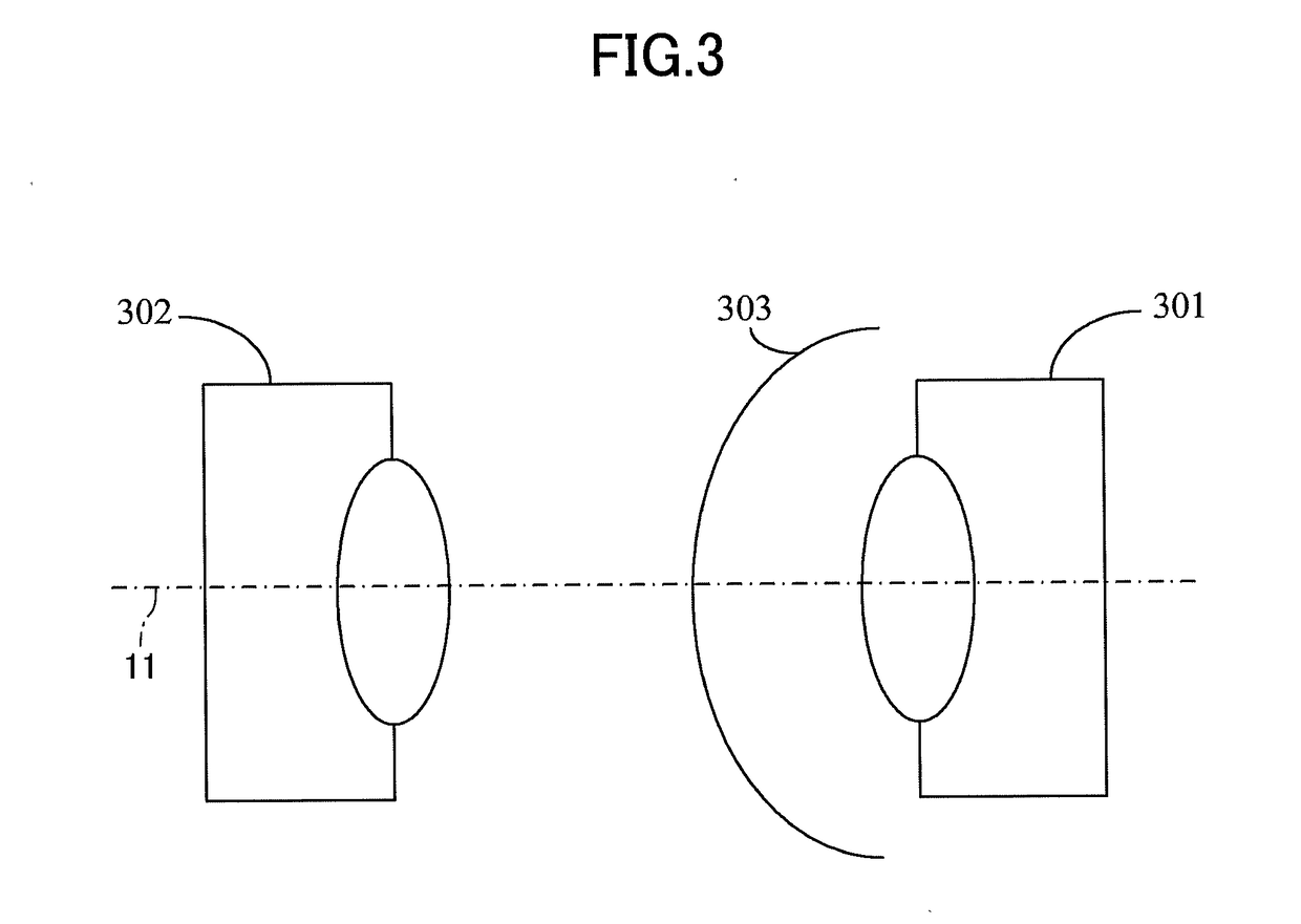
[0024]FIG. 3 illustrates the fundamental structure of a camera device 300 according to this embodiment.
[0025]As shown in FIG. 3, the camera device 300 contains a first camera 301, a second camera 302, and a parabolic mirror 303.
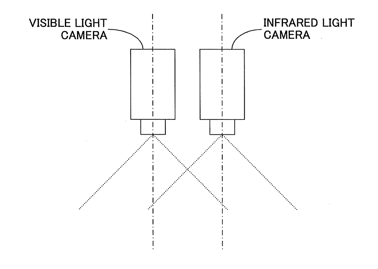
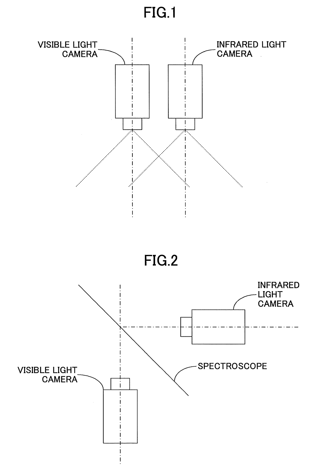
[0026]The first camera 301 includes a first lens for receiving light having a first wavelength band. The second camera 302 contains a second lens for receiving light having a second wavelength band which is different from the first wavelength band. Unlike the basic structures of the conventional multimodal cameras as presented in FIGS. 1 and 2, in the camera device 300, the first lens of the first camera 301 is disposed facing the second lens of the second camera 302. Moreover, the parabolic mirror 303 is provided between the first lens and the second lens, and may let the light having the first wavelength band penetrate and reflect the light having the second wa...
second embodiment
[0069]A method of shooting light having at least two wavelength,bands is given in this embodiment.
[0070]FIG. 8 is a flowchart of the method according to this embodiment, which is applied to the camera device 300 according to the first embodiment.
[0071]As shown in FIG. 8, the method is inclusive of STEPS S801 to S802.
[0072]In STEP S801 of FIG. 8, incident light enters the parabolic mirror 303 which is arranged between the first lens of the first camera 301 and the second lens of the second camera 302 as indicated in FIG. 3.
[0073]In STEP S802 of FIG. 8, among the incident light, light having a first wavelength band penetrates through the parabolic mirror 303, and at the same time, light having a second wavelength band is reflected by the parabolic mirror 303.
[0074]In STEP S803 of FIG. 8, the first camera 301 containing the first lens receives the light having the first wavelength band.
[0075]In STEP S804 of FIG. 8, the second camera 302 including the second lens receives the light havi...
PUM
Abstract
Camera device and method for shooting light having at least two wavelength bands are disclosed. The camera device includes a first camera containing a first lens for receiving light having a first wavelength band; a second camera including a second lens for receiving light having a second wavelength band which is different from the first wavelength band, the second lens being disposed facing the first lens of the first camera; and a parabolic mirror set between the first camera and the second camera, able to let the light having the first wavelength band penetrate therethrough, and at the same time, reflect the light having the second wavelength band. The first camera is a non-fisheye camera. The first lens is a non-fisheye lens. The second camera and the parabolic mirror form a catadioptric camera. The aperture stop of the non-fisheye lens coincides with the focal point of the parabolic mirror.
Description
BACKGROUND OF THE DISCLOSURE1. Field of the Disclosure[0001]The present disclosure relates to the field of multimodal imaging, and more particularly relates to a camera device for conducting a multimodal imaging process and a method for shooting light having at least two wavelength bands.2. Description of the Related Art[0002]A multimodal imaging system is a kind of camera system by which it is possible to take visible and invisible light (e.g., infrared light) pictures. It has been widely applied in many fields such as human face recognition, pedestrian detection, monitoring, and the like, and its purpose is to improve the ability of detection, tracking, and recognition in a case of bad weather, for example, low light, fog, rain, or snow. In terms of object detection, visible and invisible light is mutually complementary. For instance, when recognizing a human face, long-wave infrared (far-infrared) light cannot penetrate through a pair of glasses, but visible light may penetrate t...
Claims
Application Information
Patent Timeline
Application Date:The date an application was filed.
Publication Date:The date a patent or application was officially published.
First Publication Date:The earliest publication date of a patent with the same application number.
Issue Date:Publication date of the patent grant document.
PCT Entry Date:The Entry date of PCT National Phase.
Estimated Expiry Date:The statutory expiry date of a patent right according to the Patent Law, and it is the longest term of protection that the patent right can achieve without the termination of the patent right due to other reasons(Term extension factor has been taken into account ).
Invalid Date:Actual expiry date is based on effective date or publication date of legal transaction data of invalid patent.