Sensor system for blowout preventer and method of use

a technology of blowout prevention and sensor system, which is applied in the direction of electrical/magnetic measuring arrangement, survey, borehole/well accessories, etc., can solve the problems of wellbore itself, wellbore malfunction, and sudden pressure increase or “kick” in the wellbor

Inactive Publication Date: 2018-09-06
BAKER HUGHES INC
View PDF4 Cites 5 Cited by
  • Summary
  • Abstract
  • Description
  • Claims
  • Application Information

AI Technical Summary

Problems solved by technology

Well operators generally do their utmost to prevent spillage or leakage, however, the penetration of high-pressure reservoirs and formations during drilling can cause a sudden pressure increase, or “kick,” in the wellbore itself.
A large pressure kick can result in a blowout of a drill pipe casing, drilling mud, and hydrocarbons from the wellbore, resulting in a malfunction of the well.

Method used


Image

  • Sensor system for blowout preventer and method of use
  • Sensor system for blowout preventer and method of use
  • Sensor system for blowout preventer and method of use

Examples


Embodiment Construction

[0020]In the following specification and the claims, a number of terms are referenced that have the following meanings.

[0021]The singular forms “a”, “an”, and “the” include plural references unless the context clearly dictates otherwise.

[0022]“Optional” or “optionally” means that the subsequently described event or circumstance may or may not occur, and that the description includes instances where the event occurs and instances where it does not.

[0023]Approximating language, as used herein throughout the specification and claims, may be applied to modify any quantitative representation that could permissibly vary without resulting in a change in the basic function to which it is related. Accordingly, a value modified by a term or terms, such as “about”, “approximately”, and “substantially”, are not to be limited to the precise value specified. In at least some instances, the approximating language may correspond to the precision of an instrument for measuring the value. Here and th...


PUM


Abstract

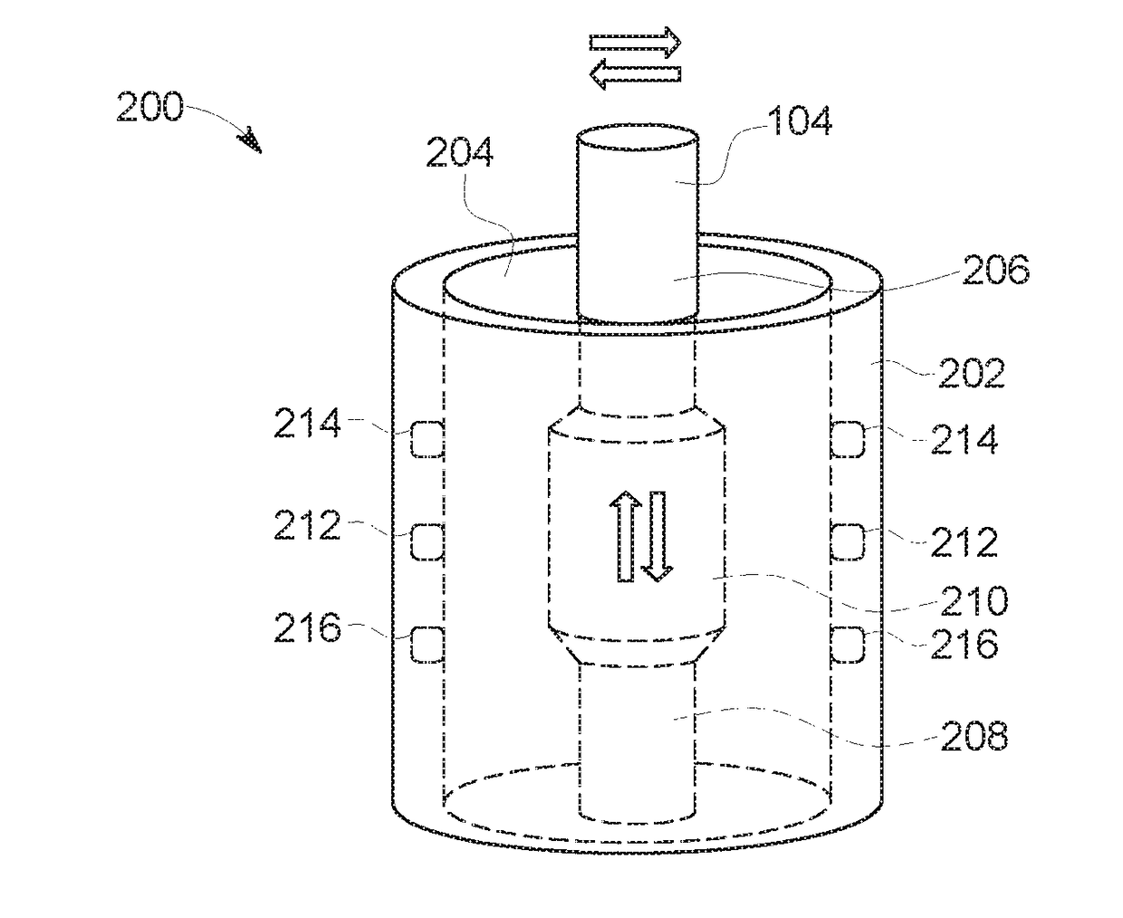
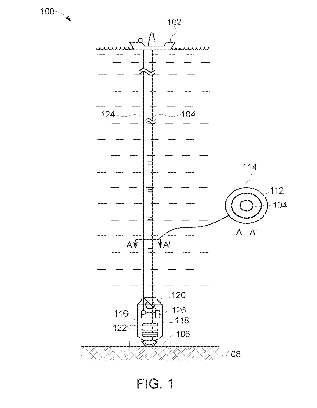
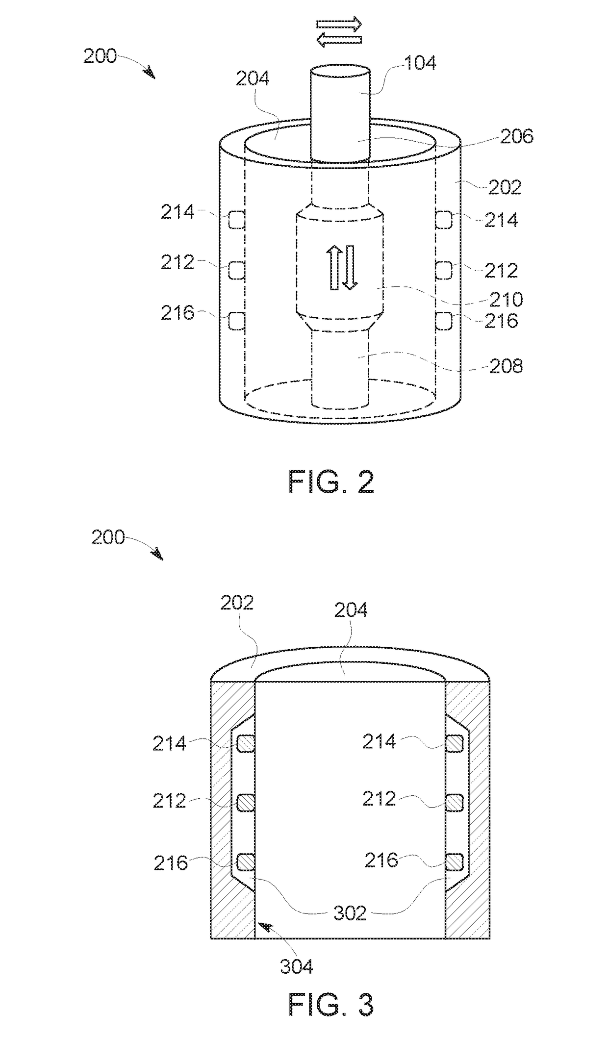
A sensor system for a sub-sea oil and gas well includes a casing, a transmit coil, a receive coil, and a processor. The casing defines an interior space through which a drilling pipe string transits. The transmit coil is coupled to the casing and is configured to conduct a current pulse and induce an electromagnetic field within the interior space. The electromagnetic field corresponds with the current pulse and interacts with the drilling pipe string. The receive coil is coupled to the casing and is configured to detect the electromagnetic field, including perturbations of the electromagnetic field due to the drilling pipe string's interaction therewith. The processor is coupled to the transmit coil and the receive coil. The processor is configured to compute a diameter of the drilling pipe string based on the current pulse and the electromagnetic field detected by the receive coil.

Description

STATEMENT REGARDING FEDERALLY SPONSORED RESEARCH AND DEVELOPMENT[0001]This invention was made with Government support under contract number 11121-5503-01 awarded by the Department of Energy. The Government has certain rights in this invention.BACKGROUND[0002]The field of the disclosure relates generally to blowout preventers and, more particularly, to a sensor system for determining position of pipe joints within a blowout preventer.[0003]Sub-sea oil and gas production generally involves drilling and operating wells to locate and retrieve hydrocarbons. Rigs are positioned at well sites in relatively deep water. Tools, such as, for example, and without limitation, drilling tools, tubing, and pipes, are employed at these wells to explore submerged reservoirs. It is important to prevent spillage and leakage of fluids from the well into the environment. Well operators generally do their utmost to prevent spillage or leakage, however, the penetration of high-pressure reservoirs and forma...

Claims


Application Information

Patent Timeline
Patent Type & Authority Applications(United States)
IPC IPC(8): E21B47/08E21B47/09E21B33/06G01B7/12
CPCE21B47/082E21B47/0905E21B33/064G01B7/12E21B33/063E21B47/09E21B33/0355E21B47/085E21B47/092E21B33/035
Inventor PLOTNIKOV, YURI ALEXEYEVICHCHEN, CHENG-POKLOPMAN, STEVENANDARAWIS, EMAD ANDARAWISMYERS, GREGORY JAY
Owner BAKER HUGHES INC
Why Eureka
Try Eureka