Display Image Projection System

a projection system and image technology, applied in the direction of control devices, instruments, vehicle components, etc., can solve the problems of requiring correction of aberrations, increasing aberrations caused by aberrations, and occurrence of aberrations, so as to reduce the size of the opening of the dashboard, suppress the occurrence of aberrations, and make the projection unit more compact.

Inactive Publication Date: 2018-09-06
YAZAKI CORP
View PDF3 Cites 7 Cited by
  • Summary
  • Abstract
  • Description
  • Claims
  • Application Information

AI Technical Summary

Benefits of technology

[0022]With the display image projection system configured as described in the above-mentioned item (1), since the optically reflecting member on the outside of the display image projection unit has the optically magnifying function, the width of the optical path of the display light emitted from the display image projection unit to the optically reflecting member can be made smaller. Hence, the display image projection unit can be made more compact easily, and the dimensions of the opening of the dashboard can also be made smaller. Moreover, since the aspherical mirror has the distortion correction function, the occurrence of aberrations can be suppressed even in the case that the magnification factor of the optical system of the HUD is made larger.
[0023]With the display image projection system configured as described in the above-mentioned item (2), since the optically reflecting member is disposed on the inside of the windshield, the surface of the windshield can be maintained in a smooth state. Since the optically reflecting member is configured as the Fresnel mirror, the optically reflecting member has a planar shape and is disposed easily on the inside of the windshield.
[0024]With the display image projection system configured as described in the above-mentioned item (3), excessive refraction and reflection can be prevented from occurring at the boundary between the optically reflecting member and the surface of the windshield. What's more, since the optically reflecting member is configured as a Fresnel mirror, the optically reflecting member has a planar shape, and the unevenness formed on the windshield can be suppressed to the minimum.
[0025]With the display image projection system configured as described in the above-mentioned item (4), since each of the aspherical mirror of the projection optical system and the optically reflecting member has the distortion correction function, the aberrations of the entire system are suppressed easily. For example, the distortion due to the curved shape of the windshield can be corrected by the optically reflecting member, and the distortion due to the characteristics inside the projection optical system can be corrected by the aspherical mirror.

Problems solved by technology

However, in the case that an image is displayed by an HUD, aberrations occur, for example, under the influence due to the characteristics of the optical system of the HUD and due to the curved-surface shape of the windshield of a vehicle that is included in the optical path of the optical system.
However, in the case that the curvatures of the lenses and mirrors disposed in the optical system of the HUD are increased, the aberrations caused thereby are also increased, and the aberrations are required to be corrected.
However, it is difficult to securely obtain a space required for accommodating a large HUD unit in the vehicle.
Moreover, in the case that a virtual image display screen is made larger, the width of the optical path of the display light emitted from the HUD unit is required to be made larger, whereby the width of the light emitting port of the HUD unit is required to be widened and the opening of the dashboard of the vehicle is required to be made larger, resulting in the enlargement of the HUD unit.
Hence, it is further difficult to mount the HUD unit in the vehicle.

Method used


Image

  • Display Image Projection System
  • Display Image Projection System
  • Display Image Projection System

Examples


first embodiment

[0037]First, the outline of the configuration and operation will be described.

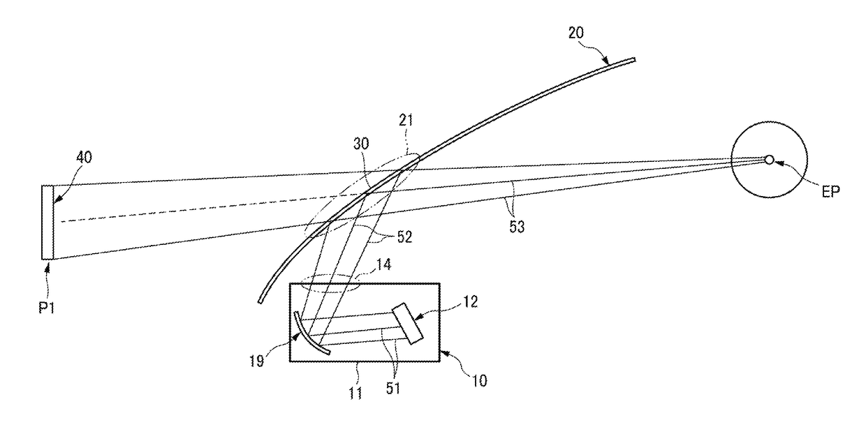
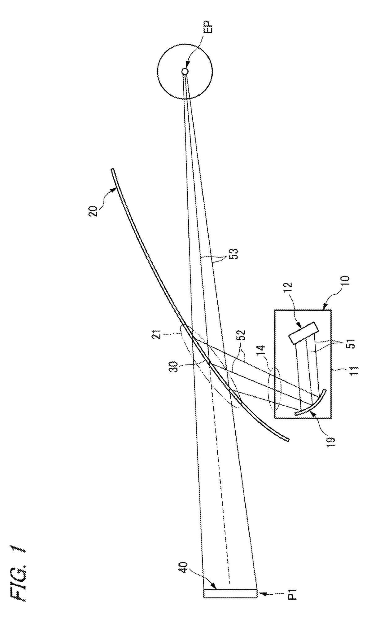
[0038]FIG. 1 shows the outline of a configuration of a display image projection system and the optical paths thereof according to an embodiment of the present invention as viewed from the side of a vehicle. Furthermore, FIG. 2 shows the internal structure of the HUD unit 10 shown in FIG. 1 and the optical paths thereof.

[0039]The display image projection system shown in FIG. 1 is intended to attain a head-up display (HUD) capable of being visually recognized by the driver on a vehicle. This display image projection system is equipped with an HUD unit 10 and a half mirror 30 with a magnifying function.

[0040]The HUD unit 10 is installed, for example, in a state of being fixed inside the dashboard ahead of the driver's seat of the vehicle. The display light emitted from the display light emitting section 14 of the HUD unit 10 passes through an optical path 52 via the opening of the dashboard and is guided to t...

second embodiment

[0074]In the above-mentioned first embodiment, although the half mirror 30 with the magnifying function has the magnifying function, only the free-curved surface mirror 19 has the distortion correction function. In the second embodiment, a half mirror 30D with a magnifying function further provided with the distortion correction function is adopted instead of the half mirror 30 with the magnifying function. Moreover, since the half mirror 30D with the magnifying function is also provided with the distortion correction function in the second embodiment, the distortion correction amount in the free-curved surface mirror 19 can be made smaller than that in the first embodiment by the amount of the correction by the half mirror 30D. The configuration and operation other than those described above are similar to those in the first embodiment.

[0075]The half mirror 30D with the magnifying function is also desired to have a planar shape because the half mirror 30D is required to be mounted ...


PUM


Abstract

An aspherical mirror or a free-curved surface mirror is disposed inside an HUD unit, and the display light of a display device is emitted to the image projection area of the windshield of a vehicle. A distortion correction function for suppressing aberrations is provided on the reflecting surface of the free-curved surface mirror. A half mirror with a magnifying function configured as a Fresnel mirror is disposed in the image projection area of the windshield, whereby the half mirror with the magnifying function is provided with a magnifying function.

Description

CROSS REFERENCE TO RELATED APPLICATIONS[0001]This application is based on and claims priority from Japanese patent application No. 2017-041695 filed on Mar. 6, 2017, the entire contents of which are incorporated herein by reference.BACKGROUND OF THE INVENTION1. Technical Field[0002]The present invention relates to a display image projection system capable of being mounted, for example, on a vehicle.2. Background Art[0003]For example, in the head-up display (HUD) apparatus disclosed in Patent Document JP-A-2004-226469, the display light emitted from an optical unit is projected to a predetermined display area on the surface of the front windshield on the inside of the compartment of a vehicle, part of the display light is reflected and guided to the eye point of the driver. Hence, the image generated by the display light is formed as a virtual image ahead of the front windshield, and the virtual image can be visually recognized by the driver. The optical unit is composed of a display...

Claims


Application Information

Patent Timeline
Patent Type & Authority Applications(United States)
IPC IPC(8): G02B27/01G02B27/09
CPCG02B27/0101G02B27/0983G02B2027/011B60K2350/2052B60K2370/334G02B2027/0194
Inventor TAKAHASHI, NOBUYUKINARUSHIMA, NORIAKI
Owner YAZAKI CORP
Why Eureka
Try Eureka