Apparatus for detecting fault of power relay of inverter

Active Publication Date: 2018-09-06
LSIS CO LTD
View PDF2 Cites 39 Cited by
  • Summary
  • Abstract
  • Description
  • Claims
  • Application Information

AI Technical Summary

Benefits of technology

[0014]According to an exemplary embodiment of the present disclosure, by employing a single voltage sens

Problems solved by technology

As a result, the initial charge resistor 11 may be damaged and may causes

Method used


Image

  • Apparatus for detecting fault of power relay of inverter
  • Apparatus for detecting fault of power relay of inverter
  • Apparatus for detecting fault of power relay of inverter

Examples


Embodiment Construction

[0020]The above objects, features and advantages will become apparent from the detailed description with reference to the accompanying drawings. Embodiments are described in sufficient detail to enable those skilled in the art in the art to easily practice the technical idea of the present disclosure. Detailed descriptions of well known functions or configurations may be omitted in order not to unnecessarily obscure the gist of the present disclosure. Hereinafter, embodiments of the present disclosure will be described in detail with reference to the accompanying drawings. Throughout the drawings, like reference numerals refer to like elements.

[0021]The embodiments of the present disclosure will hereinafter be described with reference to the attached drawings.

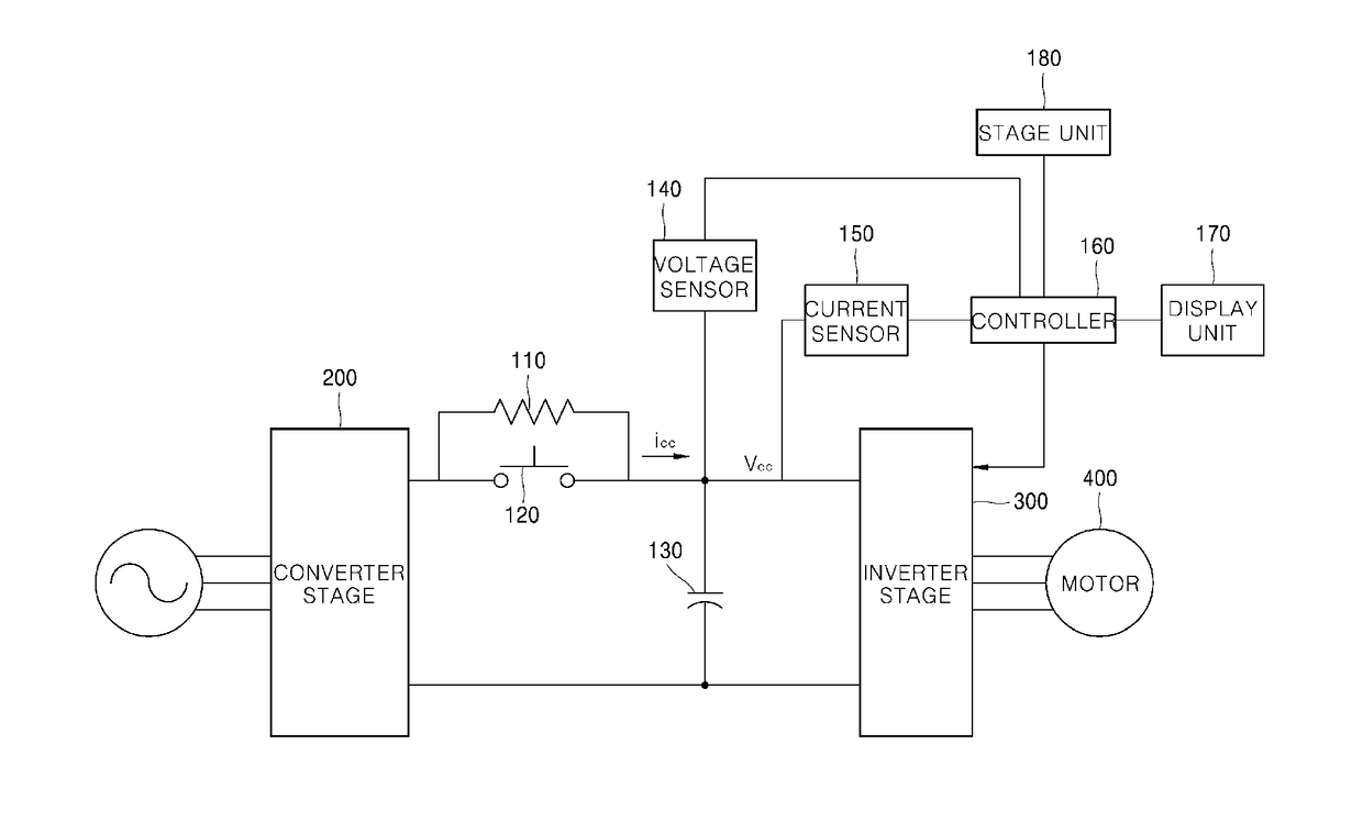
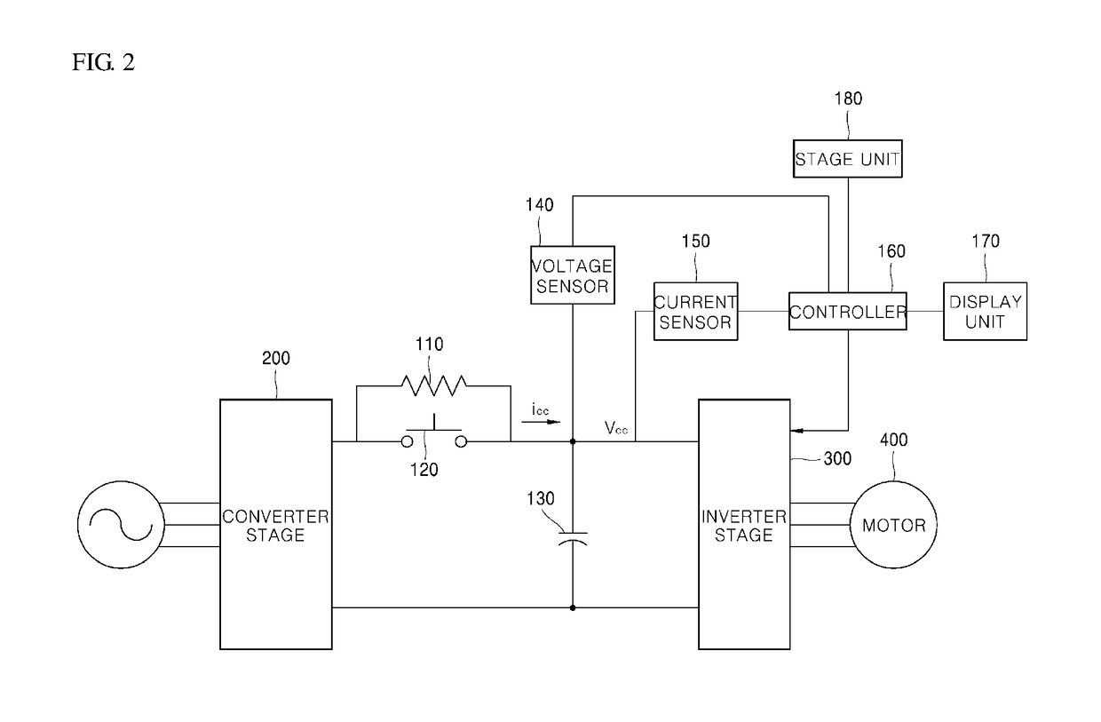
[0022]FIG. 2 is a view illustrating an apparatus for detecting a fault in a power relay of an inverter according to an embodiment of the present disclosure.

[0023]Referring to FIG. 2, the apparatus for detecting a fault in a pow...


PUM


Abstract

An apparatus for detecting a fault in a power relay of an inverter is disclosed. The apparatus for detecting a fault in a power relay includes: a voltage sensor configured to measure a voltage of a DC link; a current sensor configured to measure an output current applied to an inverter stage; a storage unit configured to store resistance of an initial charge resistor, a time constant of a capacitor, and a reference voltage measured when voltage drop of the DC link does not occur; and a controller configured to determine, when the voltage drop of the DC link occurs, the presence or absence of a fault in the power relay based on a difference between the reference voltage and a voltage measured after lapse of a period corresponding to the time constant.

Description

CROSS-REFERENCE TO RELATED APPLICATIONS[0001]This application claims the priority of Korean Patent Application No. 10-2017-0028093 filed on Mar. 6, 2017, in the Korean Intellectual Property Office, the disclosure of which is hereby incorporated by reference in its entirety.BACKGROUND1. Technical Field[0002]The present disclosure relates to an apparatus for detecting a fault in a power relay of an inverter.2. Description of the Related Art[0003]When an inverter is started, initial charging is carried out. During the initial charging, a power relay connected in parallel to an initial charge resistor is opened. The initial charge resistor serves to prevent an inrush current during the initial charging. Thereafter, the power relay of the inverter is closed using a control signal for normal operation of the inverter.[0004]FIG. 1 is a diagram illustrating a current flow during the initial charging of the inverter.[0005]Referring to FIG. 1, a converter stage 20 converts alternating current...

Claims


Application Information

Patent Timeline
IPC IPC(8): H02H1/00H02M5/40H02H7/10
CPCH02H1/0007H02H7/10H02M5/40G01R31/3278H02H3/044H02M1/32H02H9/001G01R31/3277G01R31/2836G01R19/16571
Inventor SON, JU-BEOM
Owner LSIS CO LTD
Why Eureka
Try Eureka