
Electric circuits and power systems incorporating the same

a technology of electric circuits and power systems, applied in the field of electric circuits, can solve problems such as insulation breakdown, significant damage to dc/ac power converters, and significant magnetising inrush currents

Active Publication Date: 2018-09-06
GE ENERGY POWER CONVERSION TECH
View PDF0 Cites 11 Cited by
  • Summary
  • Abstract
  • Description
  • Claims
  • Application Information

AI Technical Summary

Benefits of technology

The patent describes a circuit and method for safely and smoothly starting up a power converter. The circuit includes methods for isolating the pre-charge circuit from the main transformer and from the DC link, as well as a DC fuse to protect against failure. A resistor is also included to limit the current during the pre-charge process. The method can also control the voltage spikes when the main switchgear is opened. Overall, the patent describes a reliable and safe tool for starting up power converters.

Problems solved by technology

But closing the switchgear to reconnect the transformer to the power grid results in significant magnetising inrush currents which may be several times the rated transformer current.
In addition, when the switchgear is opened, the sudden interruption of current can lead to over-voltages within the transformer windings, which over time can result in insulation breakdown.
It is also important to pre-charge the DC link because otherwise the DC / AC power converter can suffer significant damage.
Repeatedly exposing the transformer to inrush currents by regularly closing the switchgear (e.g., each morning so that the solar plant can supply electrical power to the power grid) can seriously degrade the mechanical integrity of the transformer.
The power grid can also experience undesirable inrush spikes that can affect power quality.

Method used


Image

  • Electric circuits and power systems incorporating the same
  • Electric circuits and power systems incorporating the same
  • Electric circuits and power systems incorporating the same

Examples


Embodiment Construction

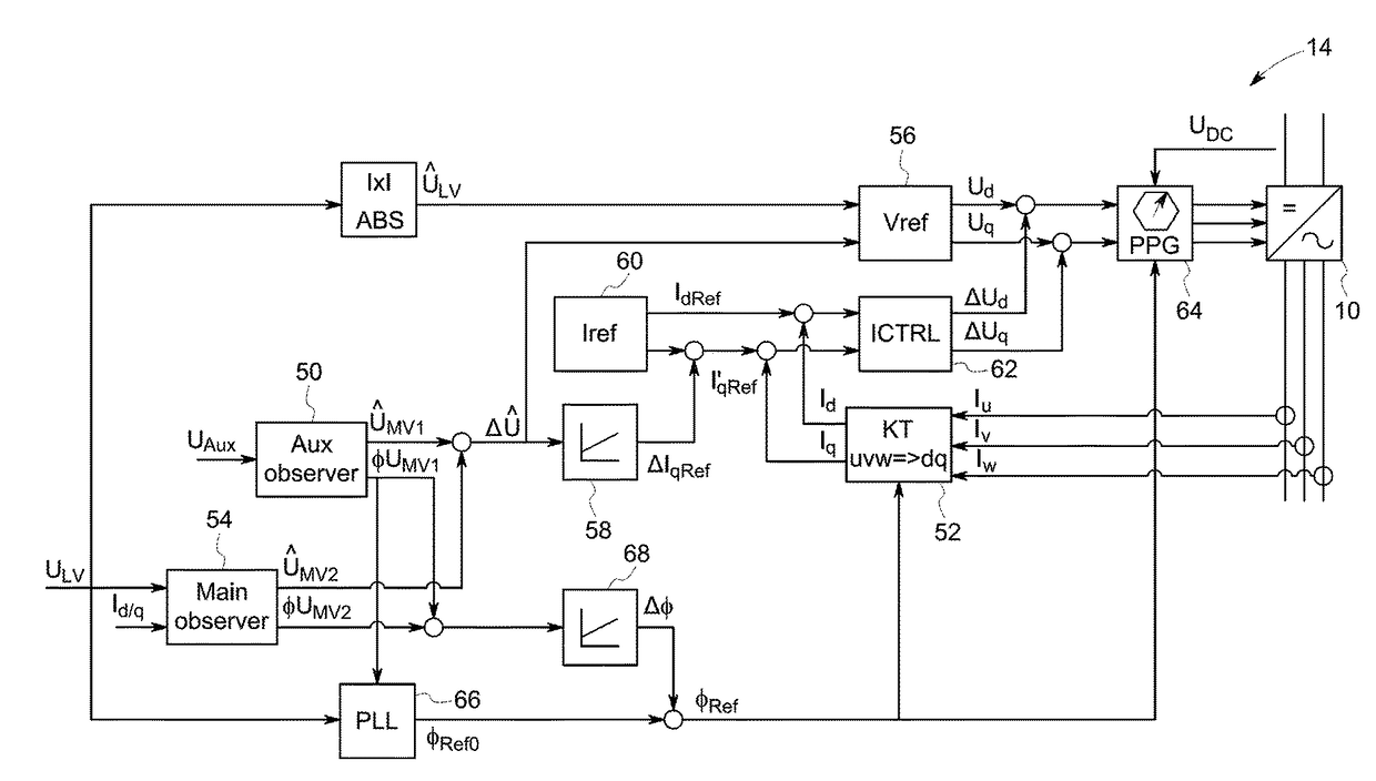
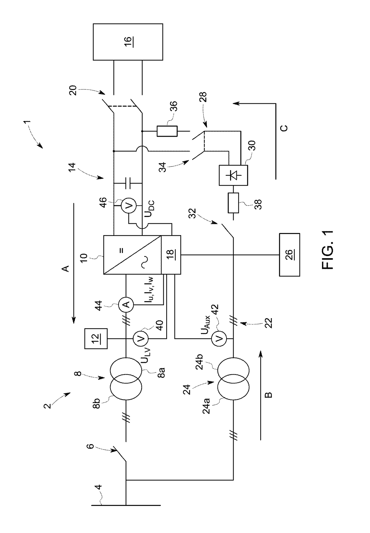
[0064]With reference to FIG. 1, a power system 1 according to the present invention includes an electric circuit connected between an AC power grid 4 carrying a medium voltage (MV) distribution voltage and a DC power source in the form of the solar farm 16. Although not shown, it will be readily understood that the electric circuit can also be connected to other types of power source or to one or more loads, e.g., as a drive circuit.

[0065]The electric circuit includes a main AC circuit 2 that is connected to the AC power grid 4. The main AC circuit 2 is a three-phase circuit and includes MV switchgear 6, a main transformer 8 having a primary winding 8a and a secondary winding 8b, and a DC / AC power converter 10. The main transformer 8 is a step-up transformer which receives LV electrical power from the DC / AC power converter 10 at the primary winding 8a and derives MV electrical power at the secondary winding 8b which is supplied to the AC power grid 4.

[0066]The main AC circuit 2 incl...


PUM


Abstract

The invention relates to a power system with an electric circuit connected between a power grid and a power source. The electric circuit includes a main power converter having main input terminals connected to the power source 16 by a DC link and output terminals. The main power converter is controlled by a controller. The electric circuit includes a main transformer having a primary winding 8a and a secondary winding, the primary winding being connected to the output terminals of the main power converter. Main switchgear is connected between the secondary winding of the main transformer and the power grid. An auxiliary transformer has a primary winding connected to the power grid in parallel with the main switchgear and a secondary winding connected to the controller. A pre-charge circuit is connected between the auxiliary transformer and the DC link.

Description

TECHNICAL FIELD[0001]The present invention relates to electric circuits, and in particular to electric circuits for connecting one or more power sources or one or more loads to a power grid.BACKGROUND OF THE INVENTION[0002]Electric circuits for connecting a power source (or a group of power sources) to a power grid are well known. In one arrangement, an electric circuit is used to connect one or more direct current (DC) power sources, e.g., photovoltaic panels of a solar plant, to a power grid or network. The electric circuit includes a DC / AC power converter with DC input terminals and AC output terminals.[0003]The DC input terminals are connected to the DC power sources by means of a DC link that typically includes one or more DC link capacitors.[0004]The AC output terminals are connected to the power grid by means of an AC circuit that includes a step-up transformer. An AC filter is typically provided on the low voltage (LV) side of the step-up transformer, i.e., between the trans...

Claims


Application Information

Patent Timeline
IPC IPC(8): H02H9/00H02J3/18
CPCH02H9/001H02J3/18H02M1/36H02J3/42H02M7/125H02J2300/20H02J3/381H02J3/382H02H9/002H02J3/38H02M1/32
Inventor SCHELENZ, OWEN JANNISBERNDT, MARKUSHOFMEYER, DOMINIK
Owner GE ENERGY POWER CONVERSION TECH
Learn More