Camera configuration method and apparatus

a technology of camera and configuration method, applied in the field of computer vision, can solve the problems of high cost of system, high cost of core device of optical motion capture system, motion capture camera, and ineffective way of properly configuring an appropriate number of motion capture cameras, and achieve the effect of saving cos

Active Publication Date: 2018-09-06
SHENZHEN REALIS MULTIMEDIA TECH CO LTD
View PDF0 Cites 1 Cited by
  • Summary
  • Abstract
  • Description
  • Claims
  • Application Information

AI Technical Summary

Benefits of technology

[0019]Unlike the conventional motion capture technologies, the number of visible cameras for each test point is calculated for each camera configuration mode in the preset view region. According to the number of visible cameras for each test point and the total number of cameras used for each camera configuration mode, the configuration cost value for each camera configuration mode can then be calculated. The final camera configuration mode

Problems solved by technology

However, the drawback is that the system is expensive, especially the core device of the optical motion capture system, the motion captur

Method used


Image

  • Camera configuration method and apparatus
  • Camera configuration method and apparatus
  • Camera configuration method and apparatus

Examples


first embodiment

The First Embodiment

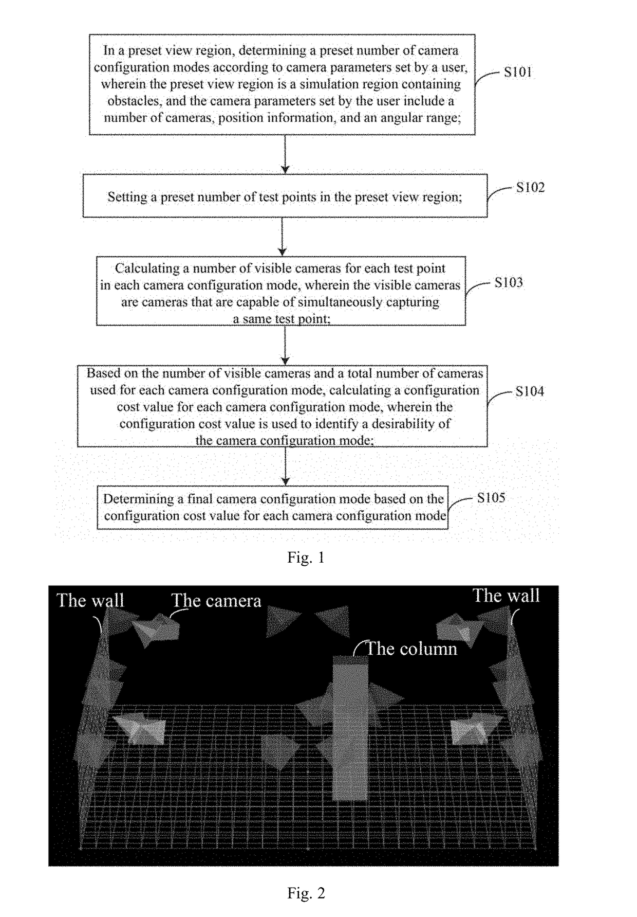
[0031]FIG. 1 is a flowchart of a camera configuration method according to a first embodiment of the present disclosure. The executing entity of the embodiment of the present disclosure may be a computer device or a functional unit in the computer device. The embodiment of the present disclosure specifically includes steps S101 to S105, as follows.

[0032]S101, in a preset view region, determining a preset number of camera configuration modes according to camera parameters set by a user, wherein the preset view region is a simulation region containing obstacles, and the camera parameters set by the user include a number of cameras, position information, and an angular range, etc.;

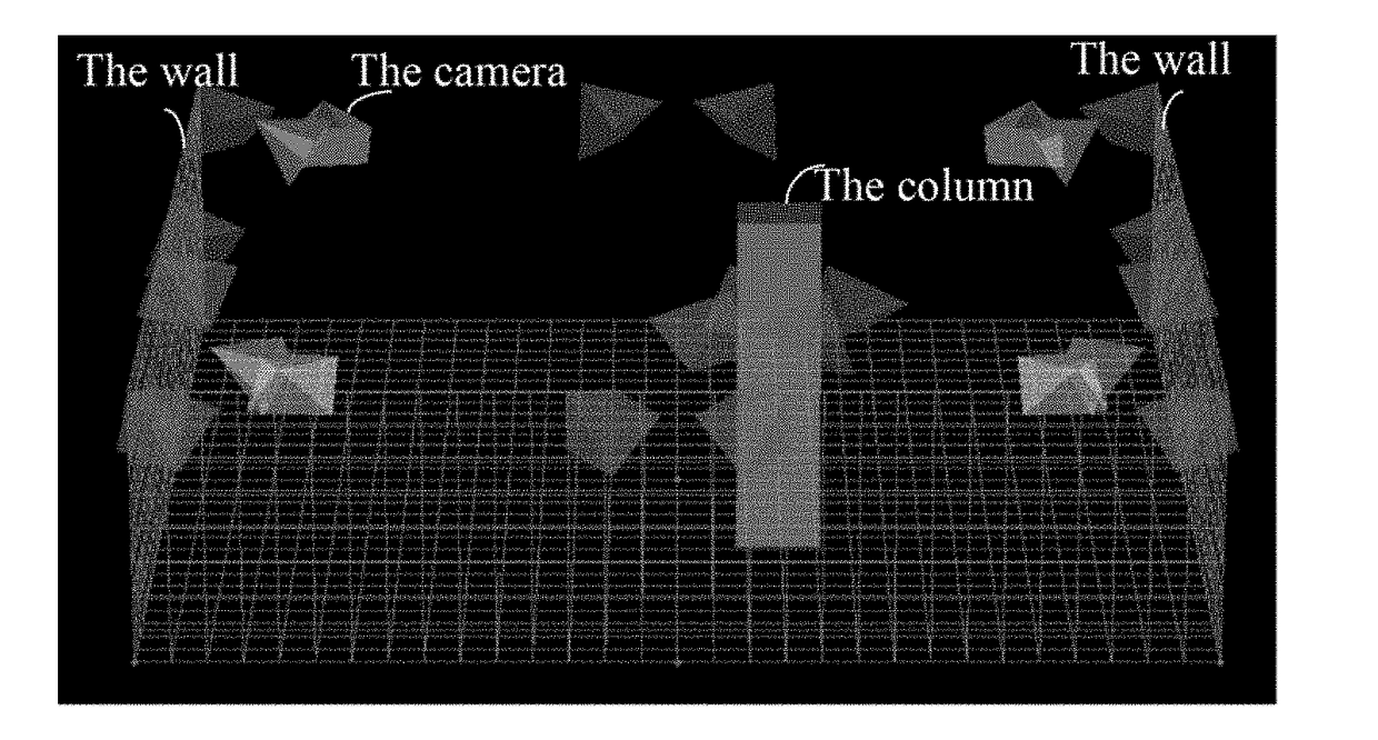
[0033]The preset view region may be a simulation region of any size and created by the user in an optical motion capture system, and the simulation region may include obstacles such as columns and walls. In the preset view region, the user can further set the camera parameters, including th...

second embodiment

The Second Embodiment

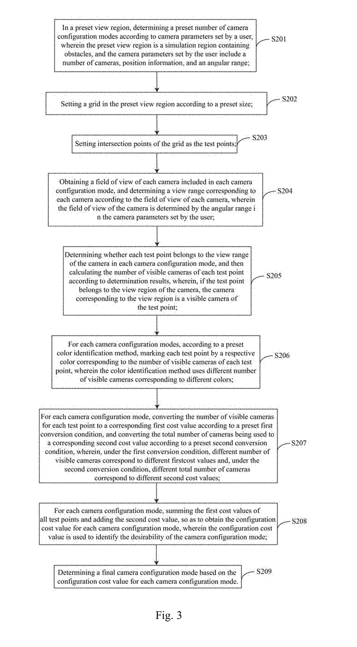
[0051]FIG. 3 is a flowchart of a camera configuration method according to a second embodiment of the present disclosure. The executing entity of the embodiment of the present disclosure may be a computer device or a functional unit in the computer device. The embodiment of the present disclosure specifically includes steps S201 to S209, as follows.

[0052]S201, in a preset view region, determining a preset number of camera configuration modes according to camera parameters set by a user, wherein the preset view region is a simulation region containing obstacles, and the camera parameters set by the user include a number of cameras, position information, and an angular range, etc.;

[0053]The preset view region may be a simulation region of any size and created by the user in an optical motion capture system, and the simulation region may include obstacles such as columns and walls. In the preset view region, the user can further set the camera parameters, including ...

third embodiment

The Third Embodiment

[0104]FIG. 7 is a schematic diagram of a camera configuration apparatus according to a third embodiment of the present disclosure. Only portions related to the embodiments of the present disclosure are shown for the convenience of explanation. A camera configuration apparatus according to the embodiment in FIG. 7 may be the executing entity of the camera configuration method provided in the first embodiment, which may be a computer apparatus or a functional unit in a computer apparatus. A camera configuration apparatus according to the embodiment in FIG. 7 includes an initialization module 31, a test point setting module 32, a quantity calculation module 33, a cost calculation module 34, and a selection module 35. The functional units are described in detail as follows.

[0105]The initialization module 31 is configured, in a preset view region, to determine a preset number of camera configuration modes according to camera parameters set by a user, wherein the prese...


PUM


Abstract

A camera configuration method solving the problem of lacking effective way to properly configure motion capture cameras in the conventional technologies, comprising: in a preset view region, determining a preset number of camera configuration modes according to camera parameters set by a user; setting a preset number of test points in the preset view region; calculating a number of visible cameras for each test point in each camera configuration mode; based on the number of visible cameras and a total number of cameras used for each camera configuration mode, calculating a configuration cost value for each camera configuration mode; and determining a final camera configuration mode based on the configuration cost value for each camera configuration mode. An effective way to properly configure the appropriate number of motion capture cameras is provided. The cost can be effectively saved while ensuring the effect of motion capture.

Description

FIELD OF THE DISCLOSURE[0001]The present disclosure generally relates to the field of computer vision and, more particularly, relates to a method and apparatus for camera configuration.BACKGROUND[0002]Motion Capture (Mocap) technology involves dimension measurement, position and azimuth measurement of an object in a physical space, etc. By placing trackers at key points of the moving object, the positions of the trackers can be captured by the motion capture system, and the motion capture technology can be used in various fields, such as animation, gait analysis, biomechanics, and ergonomics. In principle, conventional motion capture technologies can be divided into the mechanical type, acoustic type, electromagnetic type, optical type, and so on.[0003]The optical motion capture technology accomplishes the motion capture task by monitoring and tracking a specific optical spot on the target. Conventional optical motion capture technologies are mostly based on computer vision. In theo...

Claims


Application Information

Patent Timeline
IPC IPC(8): H04N5/247H04N17/00H04N5/232
CPCH04N5/247H04N17/002H04N5/23216H04N7/181G06F30/18H04N23/60H04N23/90H04N23/62
Inventor NAGASAKA, TOMOHIROYAO, JIN
Owner SHENZHEN REALIS MULTIMEDIA TECH CO LTD
Why Eureka
Try Eureka