Unlock instant, AI-driven research and patent intelligence for your innovation.

Image forming system, image forming apparatus, and image forming method

a technology of image forming and forming apparatus, applied in the field of image formation, can solve the problems of prolonged processing time and and achieve the effect of suppressing the deterioration of image quality

Inactive Publication Date: 2018-09-13
SEIKO EPSON CORP
View PDF4 Cites 2 Cited by
  • Summary
  • Abstract
  • Description
  • Claims
  • Application Information

AI Technical Summary

Benefits of technology

The present disclosure provides a method for achieving both a high-speed halftone process and suppression of the deterioration of image quality by combining the error diffusion method. The method includes a classifying unit that classifies a block of image data into a target, a determining unit that calculates an error and diffuses the error in the error diffusion method with the block as a unit, and a correcting unit that determines whether or not to arrange a dot with respect to a pixel in which there is no dot formation and corrects the dot arrangement accordingly. This method reduces the processing load and effectively prevents the disappearance of fine lines of low density and deterioration of image quality.

Problems solved by technology

In a case of the related art described above, since the systematic dither method and the error diffusion method are performed, there is a problem that a processing time is prolonged.
In order to reduce the processing time, when the method combined with the error diffusion method is changed to a method different from the general systematic dither method described above and then the method is performed in units of block the same as that of the error diffusion method, in a case where there is an edge within the block, image quality may be deteriorated due to resolution reduction.

Method used


Image

  • Image forming system, image forming apparatus, and image forming method
  • Image forming system, image forming apparatus, and image forming method
  • Image forming system, image forming apparatus, and image forming method

Examples


embodiment 1

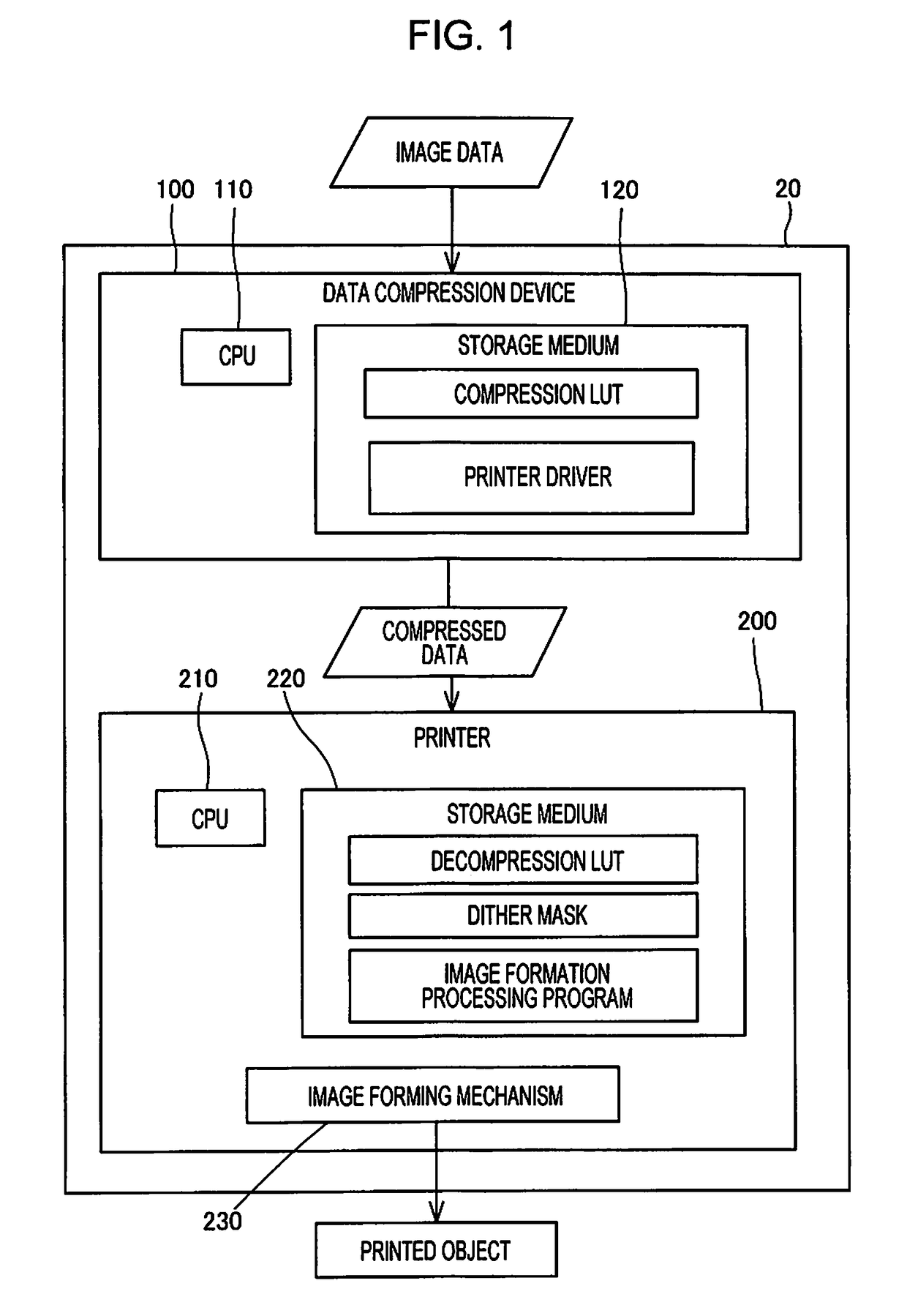
[0041]FIG. 1 schematically shows an image forming system 20. The image forming system 20 includes a data compression device 100 and a printer 200. The data compression device 100 creates compressed data by converting the image data. The compressed data is intermediate data obtained during a process of the halftone process of the image data. The data compression device 100 transmits the compressed data to the printer 200. Since the image forming system 20 includes the data compression device 100, the image forming system 20 also functions as a data compression system.

[0042]In the embodiment, the data compression device 100 is a personal computer. The data compression device 100 includes a CPU 110 and a storage medium 120. A compression LUT and a printer driver are stored in the storage medium 120. The storage medium 120 includes a RAM and performs temporal storing for performing the printer driver.

[0043]The printer 200 is an image forming apparatus. The printer 200 includes a CPU 210...

embodiment 2

[0156]Description of an embodiment 2 is mainly directed to points different from the embodiment 1. The contents which are not explicitly described are the same as those of the embodiment 1. The description of an embodiment 3 which will be described below is mainly directed to points different from the embodiment 1, and contents not explicitly described are the same as those of the embodiment 1.

[0157]In the embodiment 2, there is only one type of a dot size. That is, S=2. In the embodiment 2, a size of the block is set to 4 pixels×4 pixels=16 pixels.

[0158]The data compressing process in the embodiment 2 will be described. In the embodiment 2, the block gradation value is set to 17 gradations from 0 to 16.

[0159]FIG. 15 is a diagram showing a gradation value of a certain ink color in image data. FIG. 15 shows an excerpt of one block from the entire image data.

[0160]In a case of an example shown in FIG. 15, since the maximum gradation value is 210 and the minimum gradation value is 10, ...

embodiment 3

[0178]FIG. 25 shows an overview of a printer 20a. The printer 20a functions in the same manner as the image forming system 20 in stand-alone by performing the color conversion (S300) and a data compression program (S400). Therefore, the printer 20a configures the image forming system in a broad sense. Furthermore, the printer 20a functions as a data compression device or a data compression system. A data compressing process program and an image formation processing program are collectively referred to as an image formation program.


PUM


Abstract

A block configured with Nb pixels included in image data is classified into Nt groups, position information which is information indicating a position of the pixel configuring is created, a block gradation value is decided by a data amount smaller than a data amount required for representing gradation values of the Nb pixels based on the gradation value for each pixel configuring each group, for each of the Nt groups, dot arrangement which is information indicating the presence or absence of dot formation for each pixel configuring the block is temporarily decided based on the block gradation value, for each of the Nt groups as the target, the dot arrangement targeting the block is decided by using the temporarily decided dot arrangement and the position information, and it is determined whether or not the dot arrangement decided by the dot arrangement deciding unit is corrected by using an error diffusion method.

Description

BACKGROUND1. Technical Field[0001]The present disclosure relates to image formation.2. Related Art[0002]In JP-A-2016-116105, a technology of generating dot data indicating the presence or absence of dot formation by performing a halftone process by combining a systematic dither method and an error diffusion method is disclosed. In this technology, with respect to the systematic dither method, a gradation value of each pixel is compared to a dither threshold value to determine the presence or absence of the dot formation, and the error diffusion method is performed in units of blocks formed of a plurality of pixels.[0003]In a case of the related art described above, since the systematic dither method and the error diffusion method are performed, there is a problem that a processing time is prolonged. In order to reduce the processing time, when the method combined with the error diffusion method is changed to a method different from the general systematic dither method described abov...

Claims


Application Information

Patent Timeline
Patent Type & Authority Applications(United States)
IPC IPC(8): B41J2/21
CPCB41J2/2132H04N1/4052H04N1/4057
Inventor KAKUTANI, TOSHIAKI
Owner SEIKO EPSON CORP