
Power Electronic Converter Based Synchronizer for Generators

a technology of synchronizer and electronic converter, applied in wind energy generation, ac network circuit arrangement, electrical apparatus, etc., can solve the problems of slow synchronization, long interconnection time, and constant phase error with time, and achieve the effect of avoiding confli

Active Publication Date: 2018-09-13
MITSUBISHI ELECTRIC RES LAB INC
View PDF10 Cites 4 Cited by
  • Summary
  • Abstract
  • Description
  • Claims
  • Application Information

AI Technical Summary

Benefits of technology

The patent text describes a solution for improving the synchronization of generators in power systems. They found that by replacing the synchronization device with a faster power device, they could speed up the synchronization process without disrupting the grid. They also discovered that controlling the amplitude, frequency, and phase of the generation's output voltages with the same parameters as the power system could quickly synchronize the generators. Additionally, they found that controlling the frequency and phase with the same variable could lead to conflicts, so they designed a control system to resolve this issue. Overall, the invention allows for faster and more synchronized power systems.

Problems solved by technology

Due to the frequency difference, the phase error keeps on changing with time.
However, this results in slow synchronization and long interconnection time.
It may also lead also to a faulty synchronization, as a zero phase error cannot be ensured during the generator breaker operation.
This example demonstrates the situation where generators are located far from the point of interconnection and synchronizer, and it is not desirable to temporarily disable generator controls.
If the converter based synchronizer is activated when the frequency error is too high, the generator controls will start acting before the synchronization is complete and will nullify the effect of the synchronizer.
However, FIG. 9 shows that the phase control becomes unstable for bandwidths above 0.12 Hz.
This is due to the limited rating of the converter based synchronizer.
This results in the reduction in the frequency control bandwidth.
Even after knowing the gain of the saturation block due to the limited synchronizer rating, it is not possible to directly obtain the frequency domain response of the frequency and phase control loop gains.
Moreover, if generator controls are disabled during synchronization, then
Nonetheless, the design condition in (19) can be easily used as a thumb rule, leading to only slight conservative design.
It is evident that a lower rating of the disclosed converter based synchronizer increases the time required for the synchronization process.
Hence, there is a trade-off between the cost of the converter based synchronizer and performance of the synchronization process.

Method used


Image

  • Power Electronic Converter Based Synchronizer for Generators
  • Power Electronic Converter Based Synchronizer for Generators
  • Power Electronic Converter Based Synchronizer for Generators

Examples


Embodiment Construction

[0047]The following description provides exemplary embodiments only, and is not intended to limit the scope, applicability, or configuration of the disclosure. Rather, the following description of the exemplary embodiments will provide those skilled in the art with an enabling description for implementing one or more exemplary embodiments. Contemplated are various changes that may be made in the function and arrangement of elements without departing from the spirit and scope of the subject matter disclosed as set forth in the appended claims.

[0048]Specific details are given in the following description to provide a thorough understanding of the embodiments. However, understood by one of ordinary skill in the art can be that the embodiments may be practiced without these specific details. For example, systems, processes, and other elements in the subject matter disclosed may be shown as components in block diagram form in order not to obscure the embodiments in unnecessary detail. In...


PUM


Abstract

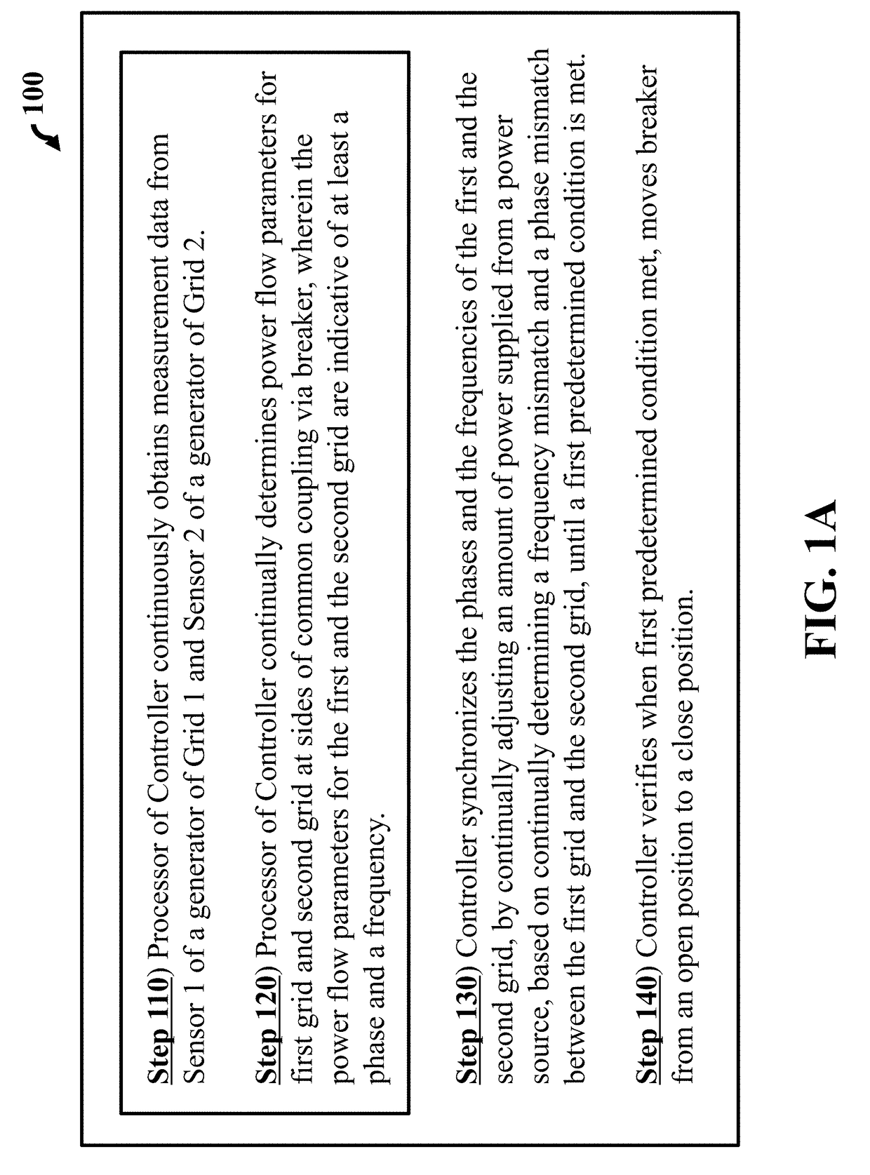
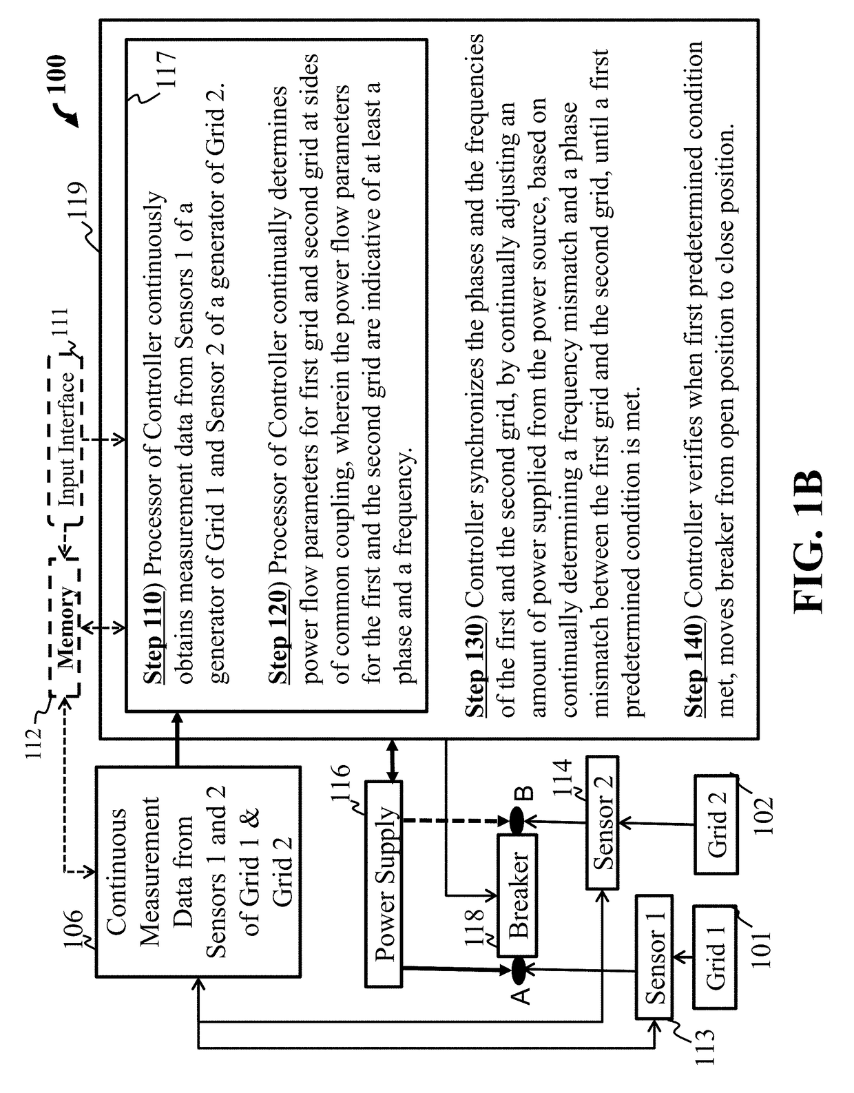
A power system including a first grid and a second grid, each grid having power flow parameters. A breaker installed at a point of common coupling between the first grid and second grid. A first sensor and a second sensor, each located on a side of the point of the common coupling for continually determining the power flow parameters of the first grid and second grid. Wherein the power flow parameters for the first and second grid are indicative of a frequency and a phase. A power source for supplying power to either the first grid or second grid. A controller for synchronizing the frequencies and the phases of the first and second grid, by continually adjusting an amount of power supplied, based on continually determining a frequency mismatch and a phase mismatch between the first grid and second grid, until a first predetermined condition is met.

Description

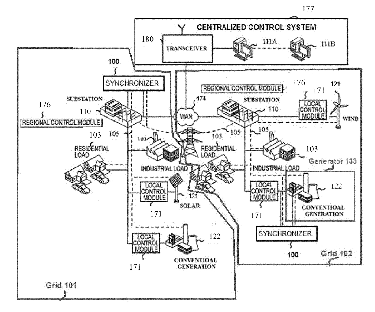
FIELD[0001]The present disclosure relates generally to controlling of generation units in electric power systems, and more particularly to synchronization of a generation unit or a group of distributed generation units to an electric power system.BACKGROUND[0002]Electric power systems have multiple generation units that operate in synchronism under a normal operation. That is, frequency, phase, and amplitude of voltages at the terminals of a generator hold a fixed relationship with the same parameters of the remaining generators in the power system. Before a generator can be connected to an electric power system, the frequency, phase, and amplitude of the voltages at its bus need to be matched with those of the power system at the point of interconnection. Once, the so called synchronization parameters are matched within a desired tolerance, the generator breaker is closed. Any mismatch in the synchronization parameters during connection of a generation unit by a generator breaker m...

Claims


Application Information

Patent Timeline
IPC IPC(8): H02J3/38H02J13/00
CPCH02J3/383H02J13/0006H02J3/386H02J3/08H02J2310/10Y02E10/56Y02E10/76H02J3/00H02J3/38
Inventor SUN, HONGBOSHAH, SHAHIL
Owner MITSUBISHI ELECTRIC RES LAB INC
Learn More