Radiation image capturing apparatus

a technology of radiation image and capturing apparatus, which is applied in the direction of radioation controlled devices, instruments, television systems, etc., can solve the problems of unnecessarily increasing power consumption of radiation image capturing apparatus, unable to start moving image capturing at the timing intended by the photographer, and weight of the apparatus becomes heavy, so as to reduce temperature drift, increase weight and power consumption, the effect of high-speed readout of image data

Active Publication Date: 2018-09-20
KONICA MINOLTA INC
View PDF5 Cites 1 Cited by
  • Summary
  • Abstract
  • Description
  • Claims
  • Application Information

AI Technical Summary

Benefits of technology

[0011]The present invention has been made in view of the above points, and an object thereof is to provide a radiation image capturing apparatus capable of capturing a moving image, in which the moving image capturing can be immediately started without incurring increases in weight and power consumption, and both high-speed readout of image data and suppression and reduction of temperature drift can be realized.

Problems solved by technology

However, when the readout IC is warmed up before the start of the moving image capturing in order to prevent the temperature drift due to a temperature change and the like of the readout IC as described above, a photographer such as a radiologist has to wait until the warm-up of the radiation image capturing apparatus is completed even in a case where the photographer wishes to immediately start the moving image capturing, and there is a possibility that the moving image capturing cannot be started at a timing intended by the photographer.
Further, when the readout IC is energized before the capturing as described above, there is a possibility that power consumption in the radiation image capturing apparatus is unnecessarily increased.
Further, in a case where a cooling mechanism is provided as in JP 2013-176563 A, particularly when the cooling mechanism is provided in a portable type radiation image capturing apparatus, for example, the radiation image capturing apparatus becomes thick in a thickness direction (an irradiation direction of radiation), which may cause problems that the portable type radiation image capturing apparatus becomes unable to be loaded in a cassette holder of an image capturing base, weight of the apparatus becomes heavy, and the like.

Method used


Image

  • Radiation image capturing apparatus
  • Radiation image capturing apparatus
  • Radiation image capturing apparatus

Examples


configuration example 1

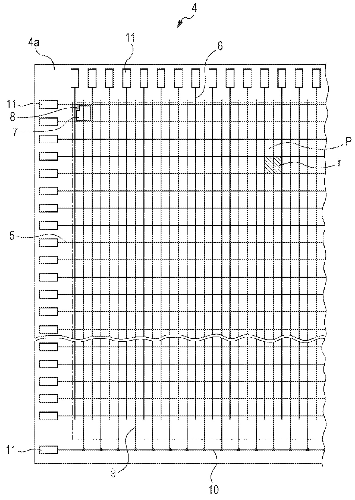
[0118]For example, as Configuration Example 1 of the mechanism for changing the reference value Vcr, the mechanism can be configured as illustrated in FIG. 10. That is, in this case, the mechanism for changing the reference value Vcr includes, in addition to the configuration illustrated in FIG. 5 similar to the conventional configuration, a capacity 25 having one terminal connected to the signal line 6 and the other terminal connected to a switch 26, and the switch 26 capable of switching the capacity 25 between on and off. Note that the state where the capacity 25 is turned on is a state where on-voltage is applied to the capacity 25 and the state where the capacity 25 is turned off is a state where off-voltage is applied to the capacity 25. Further, the capacity 25 can be formed by a capacitor, for example.

[0119]The capacity 25 and the switch 26 can be formed at an end of each signal line 6 on the sensor substrate 4 (see FIG. 2 and the like) as illustrated in FIG. 11, for example...

configuration example 2

[0138]Further, as illustrated in FIG. 14, a pseudo switching element 27 may be provided instead of the capacity 25 in the above Configuration Example 1. With such a configuration, since a parasitic capacitance is generated in the pseudo switching element 27, the pseudo switching element 27 acts in the same manner as the capacity 25 in Configuration Example 1.

[0139]Also in this case, the pseudo switching element 27 is switched between on and off by application of the on-voltage or the off-voltage from the switch 26 to the pseudo switching element 27, and by controlling on / off of the pseudo switching element 27 in the same manner as the on / off control of the capacity 25 described with reference to FIG. 12, it is possible to obtain an effect exactly the same as that of the case of Configuration Example 1 (see FIGS. 13A to 13C).

[0140]Note that an end of the pseudo switching element 27 on a side opposite to an end connected to the signal line 6 (see a in FIG. 14) may be an open end (that...

configuration example 3

[0141]Further, in the above Configuration Examples 1 and 2, the case where the capacity 25, the switch 26, the pseudo switching element 27, and the like are additionally provided has been described. However, without requiring such new configurations, the existing configurations of the radiation image capturing apparatus 1 illustrated in FIGS. 4 and 5 are used to make the existing configuration function as in the above Configuration Examples 1 and 2.

[0142]That is, in Configuration Example 3, the voltage value Vout output from the operational amplifier 18a of the integrating circuit 18 is changed as illustrated in FIG. 12 and the like when the reference value Vcr is sampled and held by use of, instead of the capacity 25, the pseudo switching element 27, and the like in Configuration Examples 1 and 2, the scan driver 15 (see FIG. 4), the scanning line 5, the TFT 8 serving as the switching element of the radiation detection element 7, and the like which are existing configurations in th...


PUM


Abstract

A radiation image capturing apparatus includes: scanning lines and signal lines; radiation detection elements; a scan driver switching a switching element of the radiation detection elements between on and off; and a readout IC incorporating readout circuits reading, as image data, electric charges from each radiation detection element, the readout circuit including: an integrating circuit outputting a voltage value corresponding to the electric charges; a reset switch resetting the integrating circuit; a first sample-and-hold circuit holding, as a reference value, the voltage value before the electric charges flow; a second sample-and-hold circuit holding, as a signal value, the voltage value after the electric charges flow; and a difference circuit outputting difference between the signal value and the reference value, the radiation image capturing apparatus further including a mechanism changing the voltage value from completion of the resetting and turning off of the reset switch until holding of the reference value.

Description

CROSS-REFERENCE TO RELATED APPLICATIONS[0001]The present application claims priority under 35 U.S.C. § 119 to Japanese Patent Application No. 2017-050294, filed on Mar. 15, 2017, the entire disclosure of which are incorporated herein by reference.BACKGROUNDTechnological Field[0002]The present invention relates to a radiation image capturing apparatus, and particularly to a radiation image capturing apparatus capable of capturing a moving image.Description of the Related Art[0003]There have been developed various radiation image capturing apparatuses, such as a so-called direct type radiation image capturing apparatus that generates electric charges with detection elements according to doses of emitted radiation and converts the electric charges into electric signals, and a so-called indirect type radiation image capturing apparatus that converts emitted radiation into electromagnetic waves of other wavelength such as visible light or the like by a scintillator or the like, thereafte...

Claims


Application Information

Patent Timeline
Patent Type & Authority Applications(United States)
IPC IPC(8): H04N5/378G01T1/20H01L27/146
CPCH04N5/378G01T1/2018H01L27/14636H01L27/14609G01T1/247H04N5/32H04N25/616H04N25/75G01T1/20184
Inventor OTA, IKUMASAKINO, KAZUHIRO
Owner KONICA MINOLTA INC
Why Eureka
Try Eureka