Assembly Having a Brake Cylinder and an Electromechanical Brake Booster

Active Publication Date: 2018-09-27
LUCAS AUTOMOTIVE GMBH +1
View PDF6 Cites 7 Cited by
  • Summary
  • Abstract
  • Description
  • Claims
  • Application Information

AI Technical Summary

Benefits of technology

[0008]It is sought to specify an assembly having a brake cylinder and having an electromechanical brake booster with a reduced structural

Problems solved by technology

Owing to their construction or their complex design, the devices known from the prior art are relatively large in term

Method used


Image

  • Assembly Having a Brake Cylinder and an Electromechanical Brake Booster
  • Assembly Having a Brake Cylinder and an Electromechanical Brake Booster
  • Assembly Having a Brake Cylinder and an Electromechanical Brake Booster

Examples


Example

[0058]It is pointed out that, in the figures described below, the toothing of the individual toothed gears, toothed racks etc. is in part illustrated merely schematically. It is self-evident that, in each case, a suitable toothing is provided, which may for example also be formed as a helical toothing, in order to permit meshing of the individual gear mechanism elements with one another.

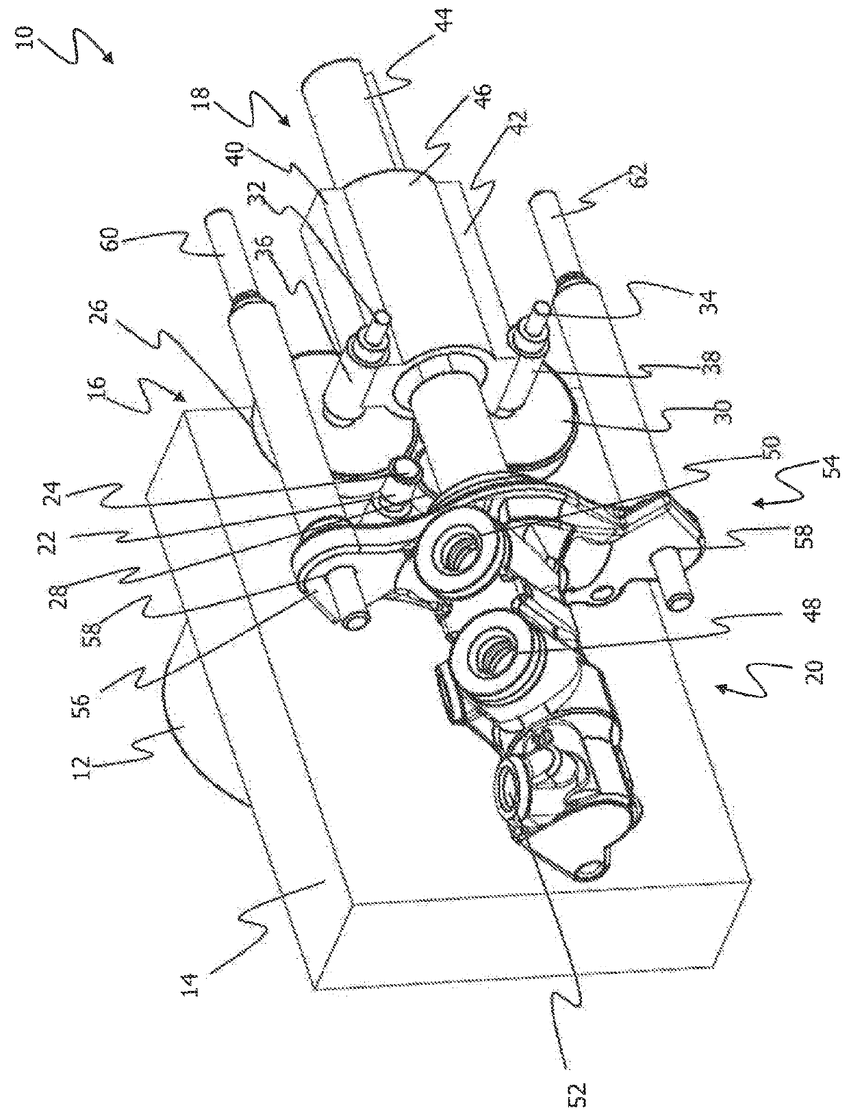
[0059]FIG. 1 shows a perspective view of an electromechanical brake booster, which is denoted generally by 10.

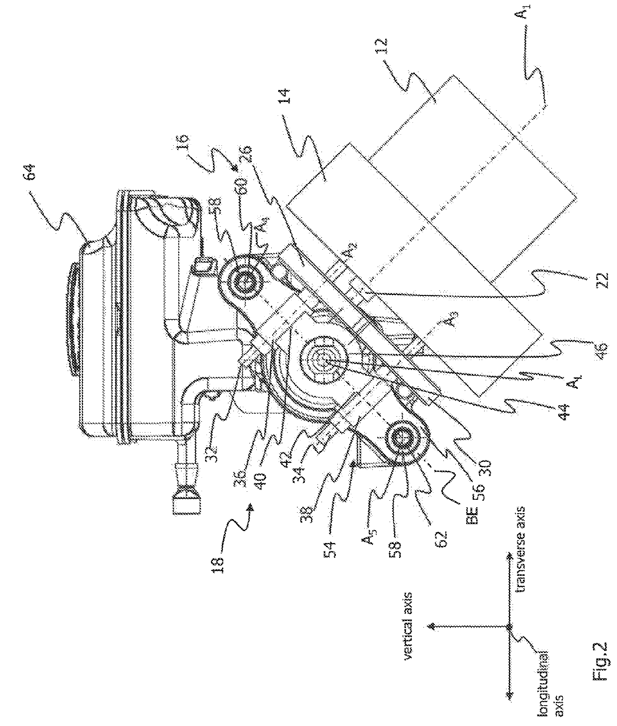
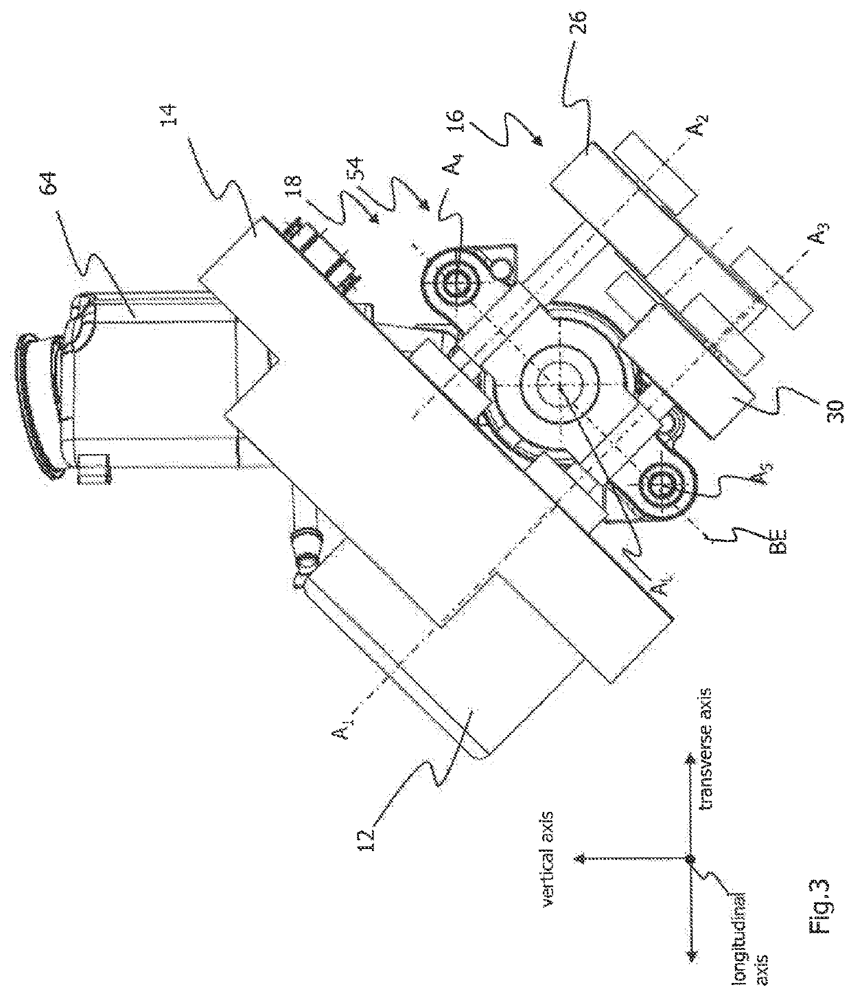
[0060]The electromechanical brake booster 10 comprises a motor 12, a control unit 14, a gear mechanism 16 and an actuating device 18. The actuating device 18 is coupled to a brake cylinder 20. The electromechanical brake booster 10 and the brake cylinder 20 form an assembly.

[0061]A pinion 24 is provided on an output shaft 22 of the electric motor 12. The pinion 24 directly drives a first spur gear 26 and an intermediate gear 28. A second spur gear 30 is driven via the intermediate gear 28.

[00...


PUM


Abstract

The invention relates to an assembly for a vehicle brake system, which comprises at least one brake cylinder and an electromechanical brake booster, having a drive arrangement for driving at least one actuating device designed for actuating a brake cylinder, wherein the drive arrangement has at least one electric motor and a gear mechanism for coupling the electric motor to the at least one actuating device, wherein at least one fastening device is provided for fastening the assembly to a vehicle, said fastening device defining a fastening plane. According to the invention the rotary shaft of the electric motor is arranged perpendicular to the longitudinal axis of the actuating device and at an angle of between 60° and 120° to the fastening plane.

Description

CROSS-REFERENCE TO RELATED APPLICATIONS[0001]This application is the National Phase of International Application PCT / EP2016 / 072054 filed Sep. 16, 2016 which designated the U.S. and that International Application was published in English under PCT Article 21(2) on Mar. 23, 2017 as International Publication Number WO 2017 / 046381 A1. PCT / EP2016 / 072054 claims priority to German Application No. 10 2015 012 125.1, filed Sep. 17, 2015. Thus, the subject nonprovisional application claims priority to DE 10 2015 012 125.1, filed Sep. 17, 2015. The disclosures of both applications are incorporated herein by reference.BACKGROUND OF THE INVENTION[0002]The present disclosure relates generally to the technical field of electrohydraulic brake force generating devices. It relates in particular to an assembly having a brake cylinder and having an electromechanical brake booster which can be used in an electrohydraulic vehicle brake system.[0003]Electromechanical brake boosters are driven by electric ...

Claims


Application Information

Patent Timeline
IPC IPC(8): B60T13/74F16H19/04F16H1/22
CPCB60T13/746B60T13/745F16H19/04F16H1/22
Inventor WINGENDER, KURTHOFMANN, MARTINKOETH, BORISCALVO MARTINEZ, JOSE MANUELSPARFELD, JENSKAMMERS, STEFANWARKENTIN, PAULDECKER, INGOHUMM, KLEMENSBAASCH, DETLEF
Owner LUCAS AUTOMOTIVE GMBH
Why Eureka
Try Eureka