Fuel evaporative gas emission suppressor

Inactive Publication Date: 2018-09-27
MITSUBISHI MOTORS CORP
View PDF0 Cites 1 Cited by
  • Summary
  • Abstract
  • Description
  • Claims
  • Application Information

AI Technical Summary

Benefits of technology

[0008]In view of the circumstances described above, an object of the present invention is to provide a fuel evaporative gas emission suppressor capable o

Problems solved by technology

In a plug-in hybrid car or any other vehicle that includes a motor in addition to an internal combustion engine and travels based primarily on drive force produced by the motor, however, there are few chances of activation of the internal combustion engine for improvement in fuel consumption, and the chance that allows abnormality detection

Method used


Image

  • Fuel evaporative gas emission suppressor
  • Fuel evaporative gas emission suppressor
  • Fuel evaporative gas emission suppressor

Examples


Embodiment Construction

[0019]An embodiment of the present invention will be described below with reference to the drawings.

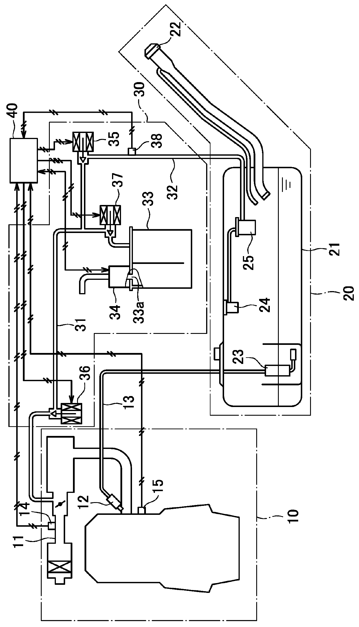
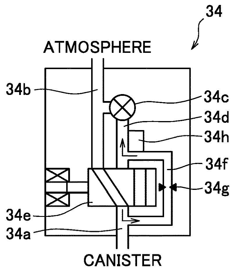
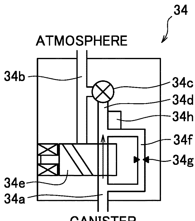
[0020]FIG. 1 is a schematic configuration diagram of a fuel evaporative gas emission suppressor 1 according to an embodiment of the present invention. FIG. 2 shows action of an internal constituent part in a case where a switching valve 34e of an evaporative leakage checking module 34 is not in operation. FIG. 3 shows action of the internal constituent part in a case where the switching valve 34e of the evaporative leakage checking module 34 is in operation. The arrows in FIGS. 2 and 3 represent the air flow direction in the case where a negative pressure pump 34c in the evaporative leakage checking module 34 is operated in the states shown in FIGS. 2 and 3. The switching valve 34e is open when it is not in operation in FIG. 2 and is closed when it is in operation in FIG. 3. The configuration of the fuel evaporative gas emission suppressor 1 will be described below.

[0021]The fuel evap...


PUM


Abstract

After an engine is started, pump monitoring is performed as follows: a canister is opened to the atmosphere; a negative pressure pump is activated; and abnormality of the negative pressure pump is evaluated on the basis of canister pressure Pc detected with a pressure sensor in an evaporative leakage check module, and after the pump monitoring is completed, a switching valve is closed so that the negative pressure pump communicates with the canister for purge any fuel evaporative gas into an intake passage of the engine, and whether or not leakage has occurred in a fuel evaporative gas emission suppressor is evaluated based on the canister pressure Pc.

Description

BACKGROUND OF THE INVENTIONField of the Invention[0001]The present invention relates to a fuel evaporative gas emission suppressor, and particularly to a technology for detecting abnormality of a fuel evaporative gas emission suppressor.Description of the Related Art[0002]To prevent discharge of a fuel evaporative gas evaporated in a fuel tank into the air, a fuel evaporative gas emission suppressor formed of a canister attached to a communication path that allows communication between the fuel tank and an intake passage of an internal combustion engine, a switching valve that opens the interior of the canister to the atmosphere or blocks the interior of the canister from the atmosphere, a sealing valve that allows communication between the fuel tank and the canister or block the communication, and a purge valve that opens and closes a communication path between the intake passage and the canister has been provided. The fuel evaporative gas emission suppressor opens the switching va...

Claims


Application Information

Patent Timeline
IPC IPC(8): F02M25/08B01D53/04F02D19/02F02M21/02
CPCF02M25/0818B01D53/0407F02D19/027F02M21/0293F02M25/0872F02D2041/225F02M2025/0881F04C2270/185F04C2270/86F02M25/08F02M25/0809F02M25/0854F02D41/22F02M25/0836F02M25/089F02D41/003F02D2250/41Y02T10/30
Inventor UEMATSU, KYOSUKEMATSUNAGA, HIDEOFURUTA, KATSUHIRO
Owner MITSUBISHI MOTORS CORP
Why Eureka
Try Eureka