
Stationary vane and centrifugal compressor provided with stationary vane

Inactive Publication Date: 2018-09-27
MITSUBISHI HEAVY IND LTD +1
View PDF2 Cites 0 Cited by
  • Summary
  • Abstract
  • Description
  • Claims
  • Application Information

AI Technical Summary

Benefits of technology

This patent describes a new design for a fluid machine that reduces fluid loss and improves efficiency. The design includes a stationary vane that generates a streamwise vortex on the side surface, which prevents the fluid from separating from the vane and breaks up any transverse vortexes that may form downstream. The vane has a simple design and can be easily manufactured. The ditches on the side surface are shaped to suppress turbulent flows and create uniform strength of the generated vortexes. Overall, this design can be used in various fluid machines to reduce fluid loss and improve efficiency.

Problems solved by technology

However, the stationary vanes provided in the flow path cause partial irregularities of the fluid in the vicinities of the stationary vanes while improving the overall flow of the fluid in the flow path.
The separation of the fluid and the generation of the transverse vortexes as described above are fluid loss and affect the efficiency of the fluid machine.
In addition, the streamwise vortex generated downstream of the stationary vane in the flow direction interferes with the transverse vortex similarly generated downstream of the stationary vane in the flow direction, and thus can break the transverse vortex.

Method used


Image

  • Stationary vane and centrifugal compressor provided with stationary vane
  • Stationary vane and centrifugal compressor provided with stationary vane
  • Stationary vane and centrifugal compressor provided with stationary vane

Examples


Embodiment Construction

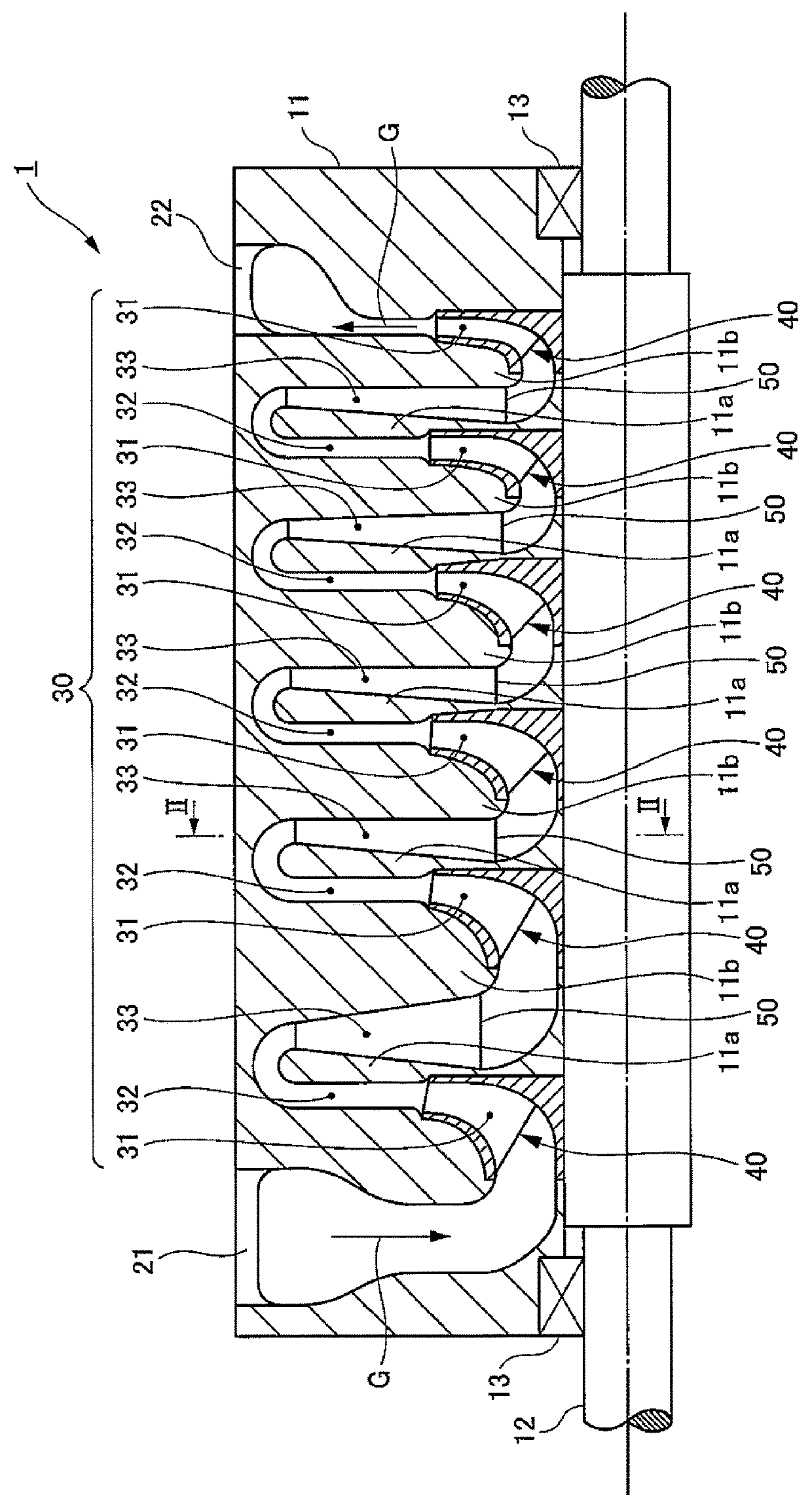
[0029]Hereinafter, embodiments of a stationary vane will be described in detail with reference to the attached drawings. Note that the following embodiments employs the stationary vane in return vanes provided in a multistage centrifugal compressor.

[0030]As a matter of course, the present invention is not limited to the following embodiments. Embodiments of the present invention may be adopted to other stationary vanes in centrifugal compressors, such as struts, inlet guide vanes, and diffuser guide vanes, or may be adopted to various stationary vanes provided in other fluid machines, such as turbochargers and pumps. In addition, it goes without saying that various modifications can be made without departing from the spirit of the embodiments of the present invention.

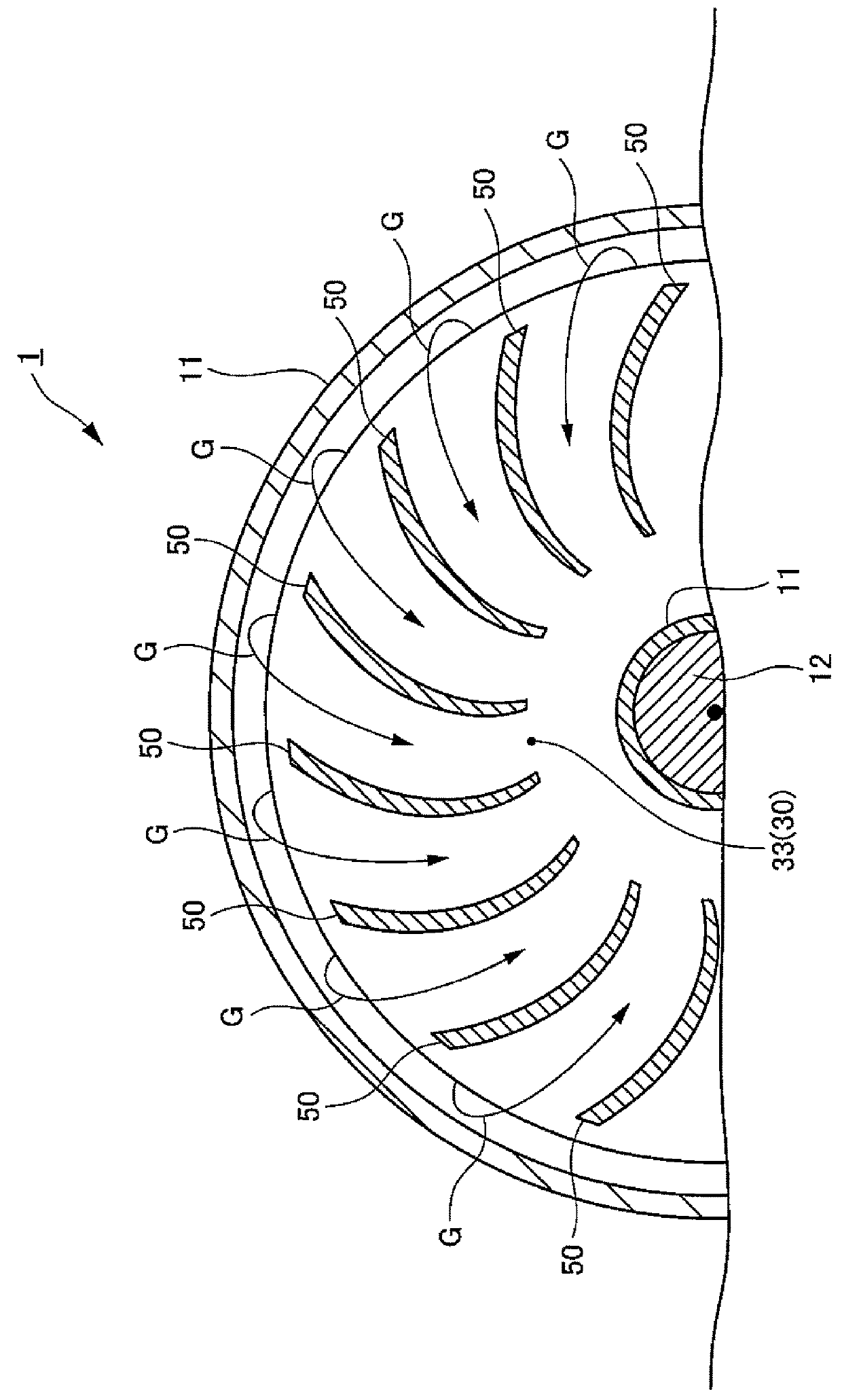
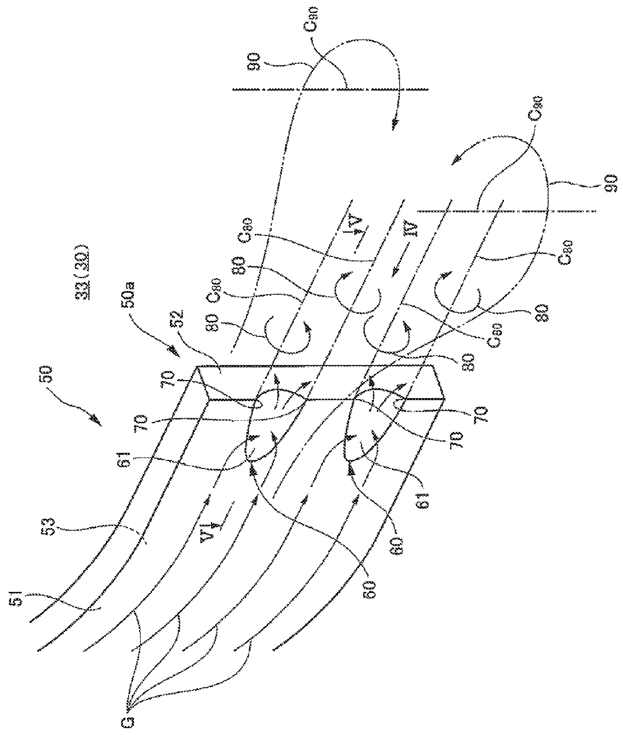
[0031]Descriptions will be provided for the structure of a centrifugal compressor including return vanes according to one or more embodiments of the present invention with reference to FIGS. 1, 2, 3A and 4A.

[0032]As ill...


PUM


Abstract

A stationary vane includes: a side surface exposed to a fluid and that is provided along a flow direction of the fluid; and corner portions provided in the side surface and that generates, at a downstream side in the flow direction of the fluid, streamwise vortexes each having a vortex axis that is parallel to the flow direction of the fluid.

Description

TECHNICAL FIELD[0001]The present invention relates to a stationary vane to be provided to a fluid machine and a centrifugal compressor provided with the stationary vane.BACKGROUND[0002]The fluid machine exchanges energy between fluid and the machine. For example, a centrifugal compressor, which is a fluid machine (driven machine), is capable of pumping (compressing) fluid, using centrifugal force by the impeller rotating together with the rotating shaft.[0003]In a fluid machine such as the centrifugal compressor described above, various stationary vanes provided in the flow path where fluid flows improve the flow of fluid and thus improve the efficiency of the energy exchange. Examples of stationary vanes to be provided to centrifugal compressors include diffuser vanes disposed downstream of the impeller in the flow direction (see Patent Document 1) and return vanes.PRIOR ART DOCUMENTPatent Document[0004]Patent Document 1: Japanese Utility Model Registration Application Publication ...

Claims


Application Information

Patent Timeline
IPC IPC(8): F04D29/44F04D17/12
CPCF04D29/444F04D17/12F04D17/122F05D2240/122
Inventor SAITO, RYOSUKE
Owner MITSUBISHI HEAVY IND LTD
Features
  • Generate Ideas
  • Intellectual Property
  • Life Sciences
  • Materials
  • Tech Scout
  • Unparalleled Data Quality
  • Higher Quality Content
  • 60% Fewer Hallucinations
Learn More