
Device for reducing wind resistance of antenna

A wind resistance and antenna technology, applied in antennas, antenna parts, damping vibration, etc., can solve the problems of antenna safety hazards, increase the wind resistance of base station antennas, and not consider the influence of the longitudinal direction of base station antennas, etc., to reduce installation and fixed costs, Ease of mass production and good market application prospects

Pending Publication Date: 2020-12-01
PROSE TECH CO LTD
View PDF0 Cites 3 Cited by
  • Summary
  • Abstract
  • Description
  • Claims
  • Application Information

AI Technical Summary

Problems solved by technology

[0004] At present, most radomes have a rectangular cross-sectional shape. This cross-sectional shape is a blunt body shape, which will significantly increase the wind resistance of the base station antenna.
In severe weather conditions such as strong winds, the greater wind resistance will make the antenna have certain safety hazards
[0005] At present, the drag reduction method of the radome is mainly to change the cross-sectional shape of the radome, so that the shape of the radome is more in line with the hydrodynamic characteristics, and this implementation method only considers the direction of changing the cross-section of the antenna, and does not consider the influence of the longitudinal direction of the base station antenna

Method used


Image

  • Device for reducing wind resistance of antenna
  • Device for reducing wind resistance of antenna
  • Device for reducing wind resistance of antenna

Examples


Embodiment Construction

[0032] The technical solutions of the embodiments of the present invention will be clearly and completely described below in conjunction with the accompanying drawings of the present invention.

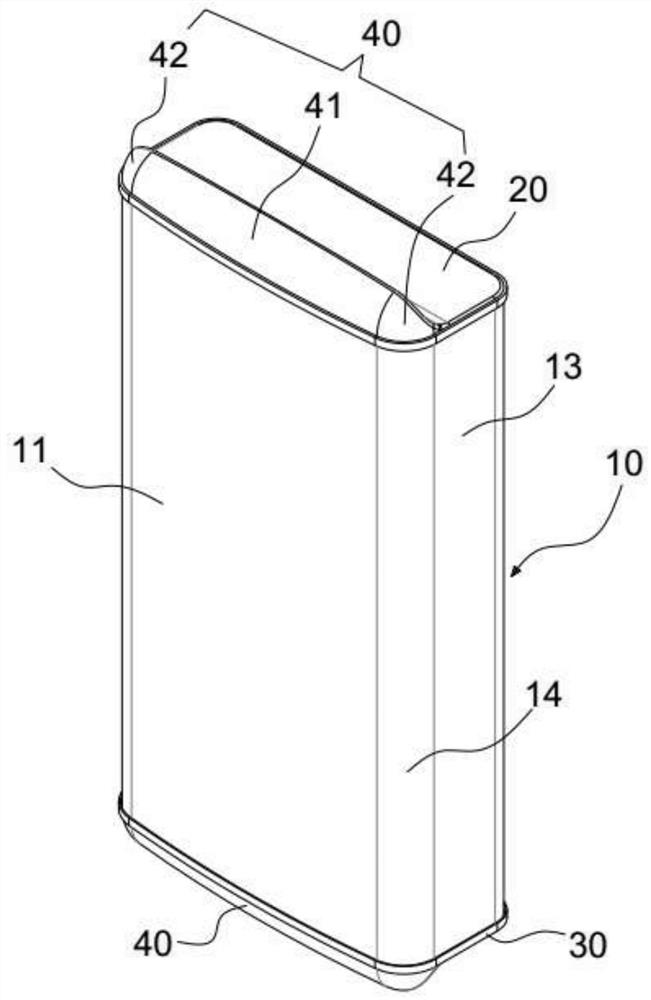
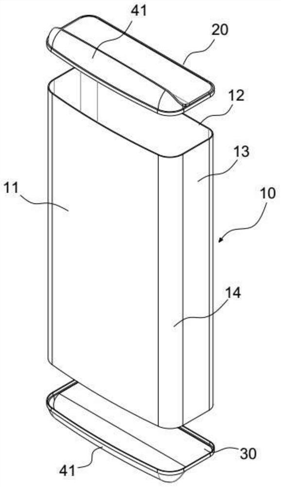
[0033] A device for reducing antenna wind resistance disclosed by the present invention is optimized by combining one or more of the radome with low resistance design, adding aerodynamic accessory drag reduction design and wake vortex control drag reduction design The design significantly reduces the wind resistance of the base station antenna, thereby improving the reliability of the antenna and reducing the installation and fixed cost of the base station antenna.

[0034] combine Figure 1 ~ Figure 4 As shown, a device for reducing antenna wind resistance disclosed by the present invention includes a radome 10, an upper end cover 20 and a lower end cover 30, and the upper end cover 20 and the lower end cover 30 are installed on the upper end and the lower end of the radome 10 respec...


PUM


Abstract

The invention discloses a device for reducing the wind resistance of an antenna, which comprises a radome and end covers arranged at the upper end and the lower end of the radome. The radome comprisesa windward side. Each end cover comprises a bottom side and a front contour surface, and each front contour surface is formed by extending from the edge corresponding to the windward side of the bottom side to the center of the end cover longitudinally. According to the invention, some contour features are arranged on the end cover of the radome, so that the fluid separation point is delayed to the tail part of the radome, the wind resistance of the antenna is reduced from the body, the reliability of the antenna is improved, and the installation and fixation cost of the base station antennais reduced.

Description

technical field [0001] The invention relates to the field of antenna systems, in particular to a device for reducing wind resistance of an antenna. Background technique [0002] At present, the mainstream construction model of the base station antenna is to use a steel structure single-tube communication tower. This tower type has the advantages of small construction radius, small project occupation, and fast construction progress. However, there are also low rigidity of the tower body and excessive horizontal displacement of the tower top. Shortcomings. Base station antennas are usually installed at a height of tens of meters, and the wind speed in the high altitude is greater, so higher requirements are placed on the reliability of the antenna. [0003] A radome is a structure that protects an antenna system from the external environment. It has good electromagnetic wave penetration characteristics in terms of electrical properties, and can withstand the effects of harsh...

Claims


Application Information

Patent Timeline
Patent Type & Authority Applications(China)
IPC IPC(8): H01Q1/42H01Q1/00
CPCH01Q1/42H01Q1/005H01Q1/246
Inventor 时均浩丁冬峰
Owner PROSE TECH CO LTD
Features
  • Generate Ideas
  • Intellectual Property
  • Life Sciences
  • Materials
  • Tech Scout
  • Unparalleled Data Quality
  • Higher Quality Content
  • 60% Fewer Hallucinations
Learn More