Charging cable assembly

a charging cable and cable technology, applied in the direction of power cables, cables, insulated conductors, etc., can solve the problem of high cooling effort and other problems

Active Publication Date: 2018-09-27
DR ING H C F PORSCHE AG
View PDF5 Cites 16 Cited by
  • Summary
  • Abstract
  • Description
  • Claims
  • Application Information

AI Technical Summary

Benefits of technology

[0005]One object of the invention is therefore to ensure cooling of the current conductor cables that is as efficient as possible in a low-cost and easy way.
[0008]In a particularly advantageous way, the heat transfer layer is formed flexibly as a gauze, mesh or film, whereby it is possible to deform the heat transfer layer in an easy way, and accordingly adapt it to the current conductor outer sheathing.
[0009]In a particularly compact advantageous embodiment, two current conductor cables and two coolant lines are arranged alternately in the clockwise direction, while there is provided a heat transfer layer which extends around the sides of the heat transfer surfaces of the coolant lines that are facing away from one another and around the sides of the current conductor outer sheathings of the current conductor cables that are facing one another. Provided in addition, or else on its own, there may be a heat transfer layer which extends around the sides of the heat transfer surfaces of the coolant lines and of the current conductor outer sheathings of the current conductor cables that are facing away from one another. In particular, this layer which extends around the sides of the current conductor outer sheathings of the current conductor cables that are facing away from one another may additionally serve as EM shielding when operating with alternating current. To ensure contact surfaces for lateral heat transfer that are as large as possible, in the charging cable assembly there may be provided a protective conductor and / or signal lines and / or filling material, which increase the compactness of the charging cable assembly.

Problems solved by technology

However, it has been found that with such assemblies a high cooling effort is required to limit excessive heating of the current conductor cables.

Method used


Image

  • Charging cable assembly
  • Charging cable assembly

Examples


Embodiment Construction

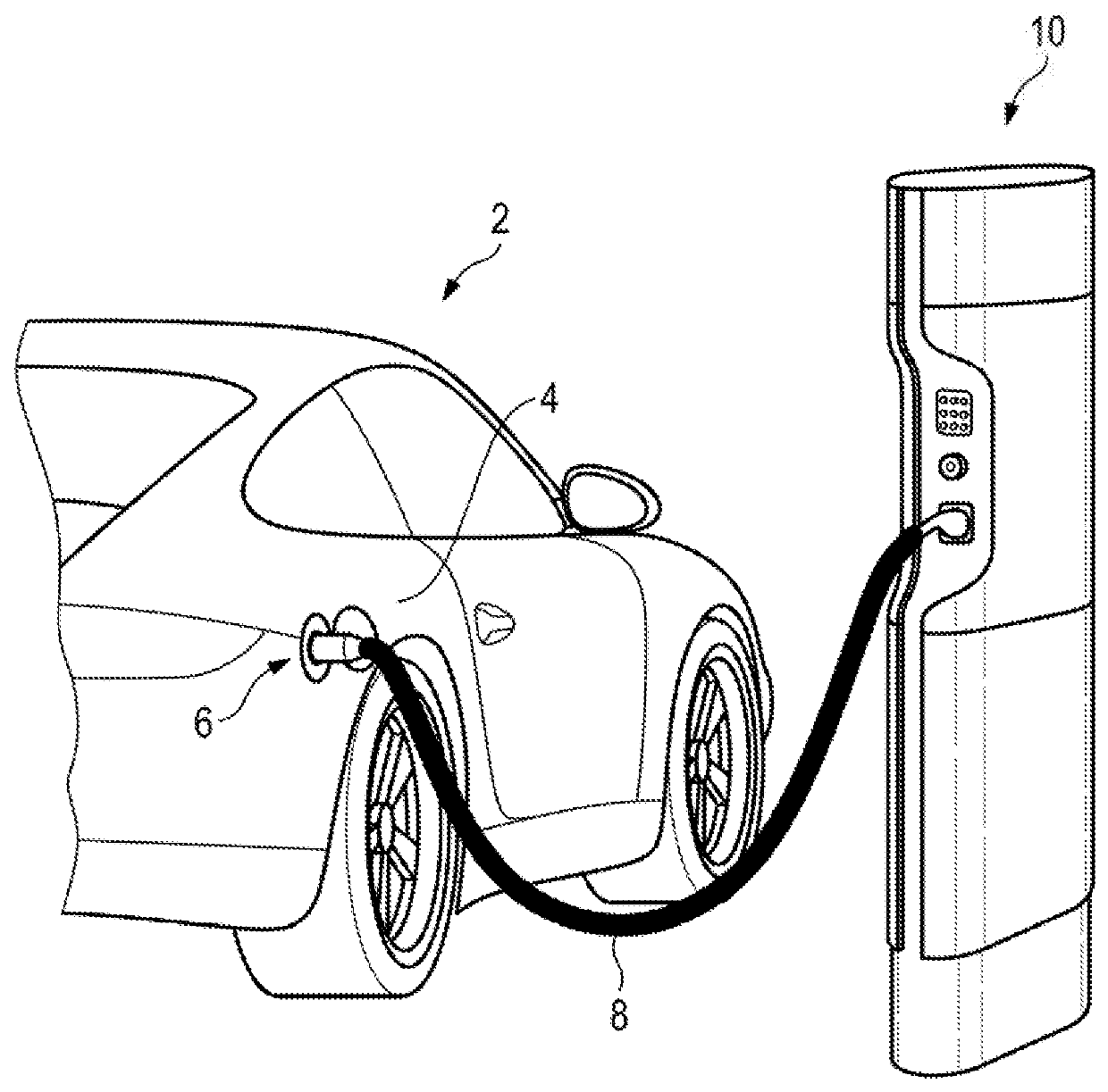
[0013]FIG. 1 shows in a perspective view a motor vehicle 2, the vehicle body 4 of which has a charging connection device 6. This charging connection device 6 is connected to a stationary electrical power supply station 10 by way of a charging cable assembly 8.

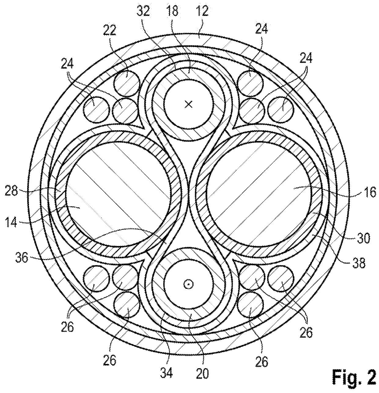
[0014]FIG. 2 shows the charging cable assembly 8 in a cross-sectional view. The charging cable assembly 8 has here a charging cable outer sheathing 12, in which two current conductor cables 14, 16 and two coolant lines 18, 20 are arranged in the present exemplary embodiment. Also provided are a protective conductor 22, signal lines 24 and filling material 26. The current conductor cables 14, 16 have in each case a current conductor outer sheathing 28, 30. The coolant lines 18, 20 have in each case a heat transfer surface 32, 34. According to aspects of the invention, a first and a second heat transfer layer 36, 38 are then provided. The heat transfer layers 36, 38 consist substantially of copper and are formed as a gauze, in or...


PUM

PropertyMeasurementUnit
electrical energyaaaaaaaaaa
heat conductingaaaaaaaaaa
heataaaaaaaaaa

Abstract

A charging cable assembly for transmitting electrical energy between a power supply station and an electrically drivable vehicle with a charging cable outer sheathing, in which at least one current conductor cable with a current conductor outer sheathing and at least one coolant line with a heat transfer surface are arranged, there being provided at least one heat transfer layer, which lies at least partially against the heat transfer surface and the current conductor outer sheathing.

Description

CROSS-REFERENCE TO RELATED APPLICATION[0001]This application claims priority to German Patent Application No. DE 10 2017 105 985.7, filed Mar. 21, 2017, which is incorporated by reference herein in its entirety.FIELD OF THE INVENTION[0002]The invention relates to a charging cable assembly for transmitting electrical energy between a power supply station and an electrically drivable vehicle with a charging cable outer sheathing, in which at least one current conductor cable with a current conductor outer sheathing and at least one coolant line with a heat transfer surface are arranged.BACKGROUND OF THE INVENTION[0003]Motor vehicles with at least one electric motor as a drive motor must be charged at charging stations in order that they can store the energy necessary for driving the motor vehicle. For this purpose, the motor vehicle has an electrical energy store and a connector, which can be connected directly or indirectly to a power supply station by means of a charging cable assem...

Claims


Application Information

Patent Timeline
Patent Type & Authority Applications(United States)
IPC IPC(8): H01B7/42H01B9/02
CPCH01B7/423H01B9/02H05K9/0098B60L11/1809B60L53/00B60L53/18H01B7/425B60L53/14H01B7/041H01B7/428H01B9/006H01B9/021B60L53/16B60L53/302B60L53/31Y02T10/70Y02T10/7072Y02T90/12Y02T90/14
Inventor REMISCH, DIRKSTAUDACHER, STEFANSTEPPER, MARCOWEBER, ERIKSCHNEIDER, BENJAMIN
Owner DR ING H C F PORSCHE AG
Why Eureka
Try Eureka