Substrate processing apparatus

a processing apparatus and substrate technology, applied in the direction of electrical apparatus, basic electric elements, electric discharge tubes, etc., can solve the problems of difficult to control the etching characteristic only and become difficult to control the etching characteristic in the edge portion of the wafer

Active Publication Date: 2018-09-27
TOKYO ELECTRON LTD
View PDF0 Cites 35 Cited by
  • Summary
  • Abstract
  • Description
  • Claims
  • Application Information

AI Technical Summary

Problems solved by technology

For this reason, when the focus ring wears and the height of the focus ring changes, it becomes difficult to control the etching characteristic in the edge portion of the wafer.
Thus, with the configuration of

Method used


Image

  • Substrate processing apparatus
  • Substrate processing apparatus
  • Substrate processing apparatus

Examples


Embodiment Construction

[0014]Embodiments of the present invention are described below with reference to the accompanying drawings. Throughout the specification and the drawings, the same reference number is assigned to substantially the same components, and repeated descriptions of those components are omitted.

>

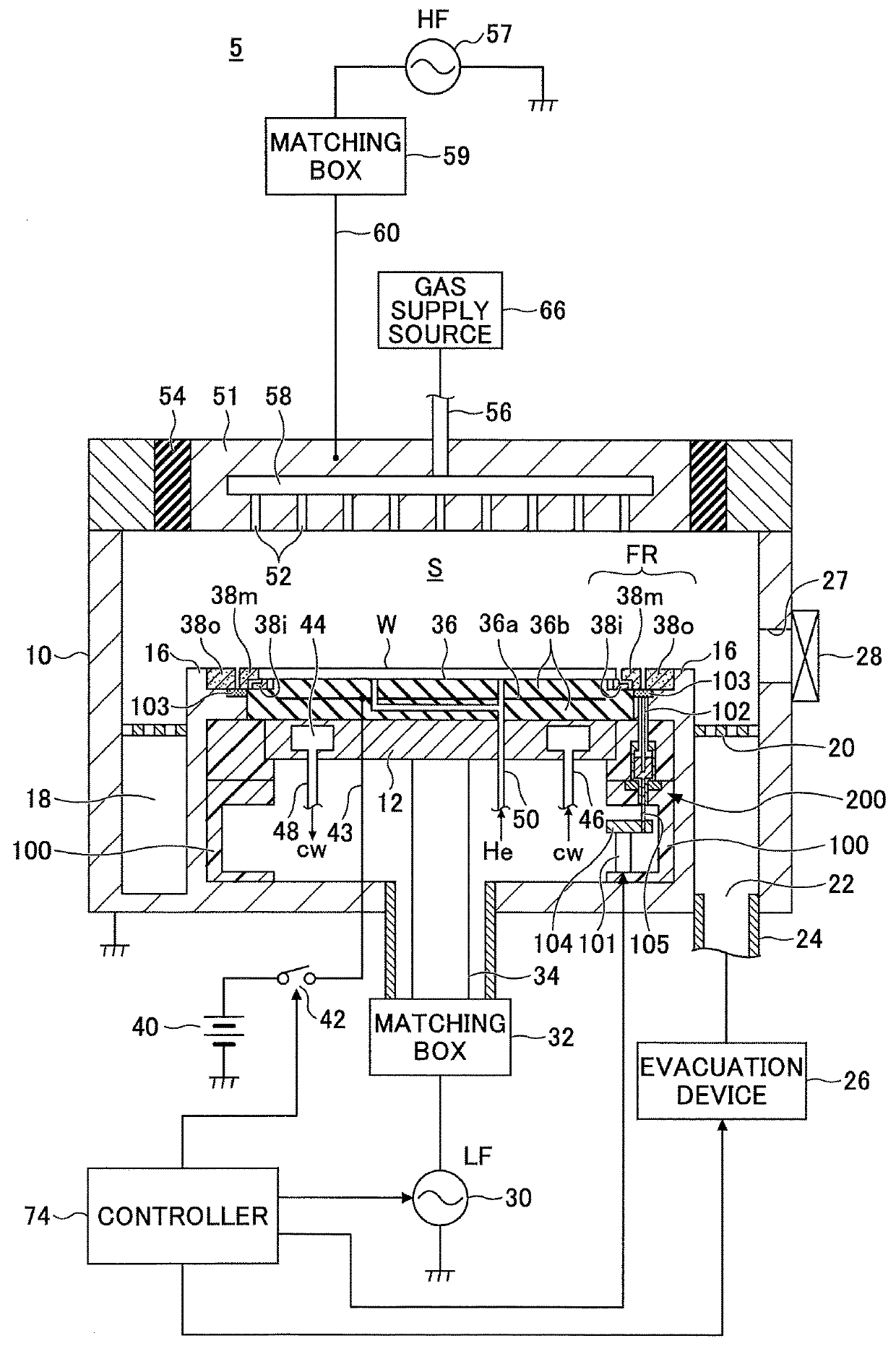
[0015]An example of a configuration of a substrate processing apparatus 5 according to an embodiment is described below with reference to FIG. 1. FIG. 1 illustrates an example of a configuration of the substrate processing apparatus 5. In the present embodiment, a parallel-plate capacitively-coupled plasma processing apparatus is used as an example of the substrate processing apparatus 5.

[0016]The plasma processing apparatus 5 includes a cylindrical vacuum chamber 10 comprised of a metal such as aluminum or stainless steel. The chamber 10 is an example of a process chamber where plasma processing is performed. The chamber 10 is grounded.

[0017]A discoidal stage 12 is disposed in the center of the bo...


PUM


Abstract

A substrate processing apparatus includes a process chamber, a stage that is disposed in the process chamber and on which a substrate is placeable, a moving mechanism, and a focus ring. The focus ring is disposed on the stage and includes an inner focus ring disposed close to the substrate placed on the stage, a middle focus ring that is disposed outside of the inner focus ring and is movable in a vertical direction by the moving mechanism, and an outer focus ring that is disposed outside of the middle focus ring.

Description

CROSS-REFERENCE TO RELATED APPLICATIONS[0001]The present application is based upon and claims the benefit of priority of Japanese Patent Application No. 2017-055977 filed on Mar. 22, 2017 and Japanese Patent Application No. 2018-041228 filed on Mar. 7, 2018, the entire contents of which are incorporated herein by reference.BACKGROUND OF THE INVENTION1. Field of the Invention[0002]An aspect of this disclosure relates to a substrate processing apparatus.2. Description of the Related Art[0003]A plasma etching apparatus includes a focus ring disposed along the circumference of a semiconductor wafer (which is hereafter referred to as a “wafer”) (see, for example, Japanese Laid-Open Patent Publication No. 2008-244274). The focus ring has a function to control plasma near the circumference of the wafer and to improve the in-plane uniformity in the etching rate of the wafer.[0004]The etching rate in an edge portion of the wafer changes depending on the height of the focus ring. For this rea...

Claims


Application Information

Patent Timeline
IPC IPC(8): H01L21/687H01L21/67H01L21/683
CPCH01L21/68735H01L21/67069H01L21/68785H01L21/6833H01J37/21H01J37/32642H01J37/3053H01L21/67109H01L21/6831H01L21/68742H01J2237/334H01J37/32091
Inventor TAKAHASHI, SHUICHIMIYADATE, TAKAHARUBANSE, TAKANORITAKAYOSHI, JOJIMORIYA, RUMIKO
Owner TOKYO ELECTRON LTD
Why Eureka
Try Eureka