Leaf spring suspension system for a vehicle
- Summary
- Abstract
- Description
- Claims
- Application Information
AI Technical Summary
Benefits of technology
Problems solved by technology
Method used
Image
Examples
Embodiment Construction
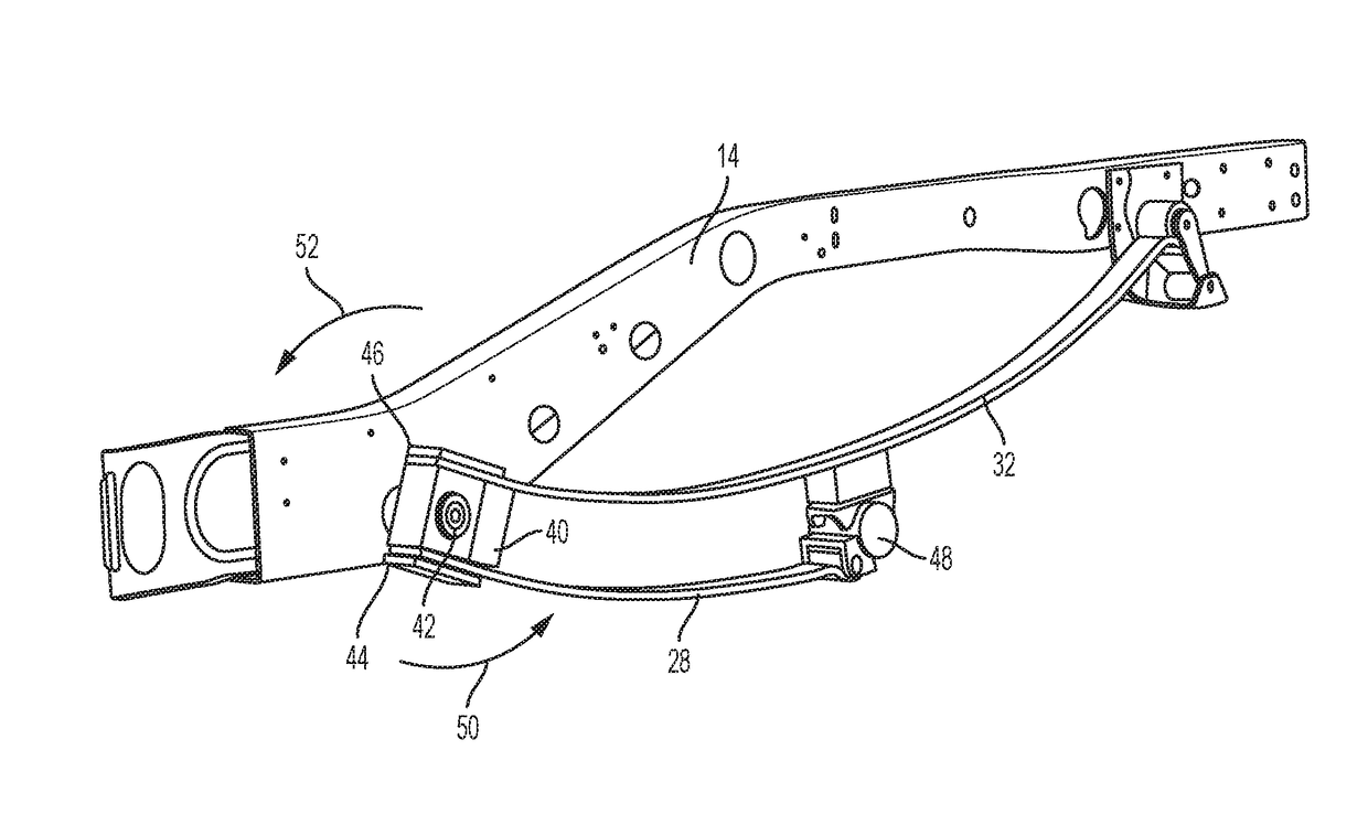
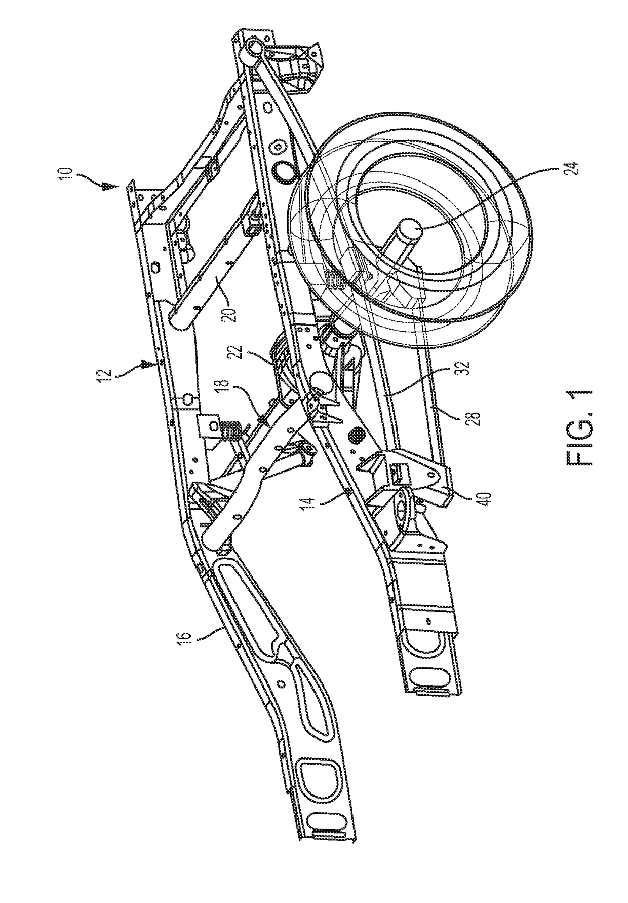
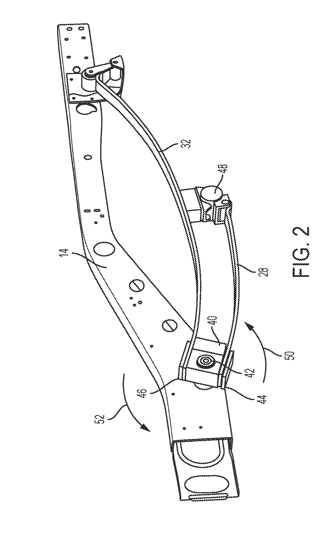
[0029]Referring to FIG. 1, illustrated is a vehicle suspension system 10 having a chassis generally designated with numeral 12. The chassis 12 includes a first chassis rail 14 and a second chassis rail 16 that are arranged substantially parallel to each other. The first and second chassis rails 14, 16 are coupled to each another by at least one cross brace, such as a first cross brace 18 and a second cross brace 20, as shown. A differential drive arrangement 22 is fixedly coupled to the chassis 12 and converts the rotary motion of a drive shaft (not shown) to substantially orthogonal rotary motion at shaft 24. The shaft 24 includes an associated pair of universal joints (not specifically designated) that are arranged to be proximal and distal with respect to the differential drive arrangement 22. Thus, the shaft 24 has an associated longitudinal axis to accommodate transaxial motion. It is to be appreciated that the shaft 24 refers to a pair of half shafts in some embodiments. The h...
PUM
 Abstract
Description
Claims
Application Information
 - R&D
- Intellectual Property
- Life Sciences
- Materials
- Tech Scout
- Unparalleled Data Quality
- Higher Quality Content
- 60% Fewer Hallucinations
Browse by: Latest US Patents, China's latest patents, Technical Efficacy Thesaurus, Application Domain, Technology Topic, Popular Technical Reports.
© 2025 PatSnap. All rights reserved.Legal|Privacy policy|Modern Slavery Act Transparency Statement|Sitemap|About US| Contact US: help@patsnap.com


