Servo actuators

a technology of servo actuators and actuators, which is applied in the direction of rotorcraft, mechanical equipment, transportation and packaging, etc., can solve the problems of increasing the size and weight of the servo actuator assembly, affecting the accuracy of the movement, and affecting the operation of the servo actuator. achieve the effect of reducing the increase in the size of the servo actuator and more precise control of the movemen

Active Publication Date: 2018-10-04
BLAGDON ACTUATION RES
View PDF5 Cites 8 Cited by
  • Summary
  • Abstract
  • Description
  • Claims
  • Application Information

AI Technical Summary

Benefits of technology

[0050]The servo actuator may include a feedback system. The feedback system may alter the behaviour of the servo actuator in dependence on the movement of the actuator member. The feedback system may be a mechanical feedback system. The mechanical feedback system may include a mechanical linkage connecting the at least one outer sleeve to the actuator member. The mechanical linkage may be arranged to control the movement of the outer sleeve relative to the actuator housing in response to movement of the actuator member. Using the outer sleeve as part of the feedback system may allow for more precise control of the movement whilst minimising the increase in size of the servo actuator associated with the inclusion of a feedback system. The feedback system may be an electrical feedback system. The electrical feedback system may include a sensor and a controller arranged to control the movement

Problems solved by technology

One mode of servo actuator failure is a “supply-failure” wherein the supply of pressurised fluid to or within the actuator is interrupted.
Having two hydraulic systems to control the same actuator may increase the size and weight of the servo actuator assembly.
Another way in which a servo actuator may fail is if the spool jams, for example as a result of contaminants in the fluid or wear of internal components.
Including such bypass valves may i

Method used


Image

  • Servo actuators
  • Servo actuators
  • Servo actuators

Examples


Embodiment Construction

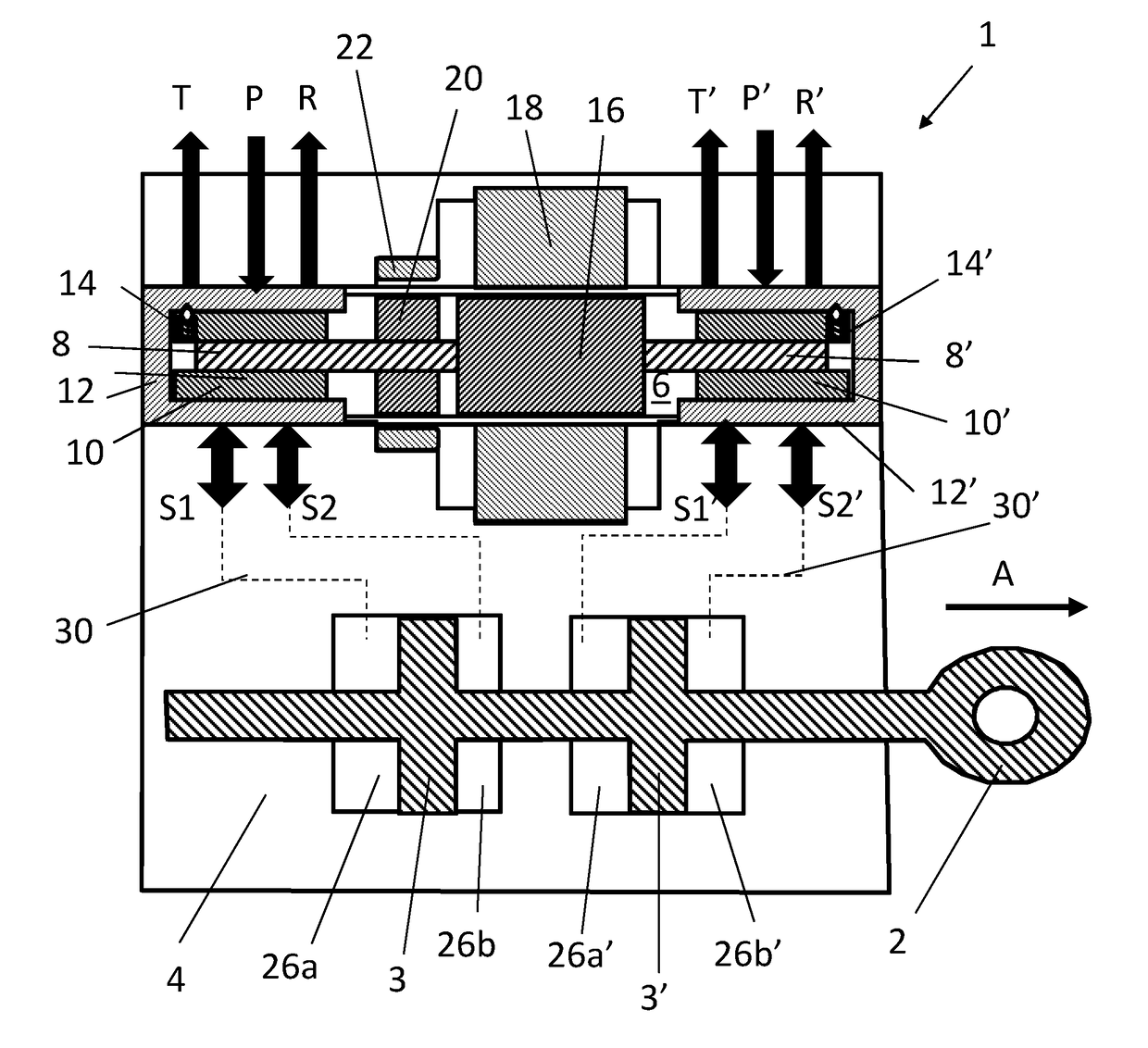
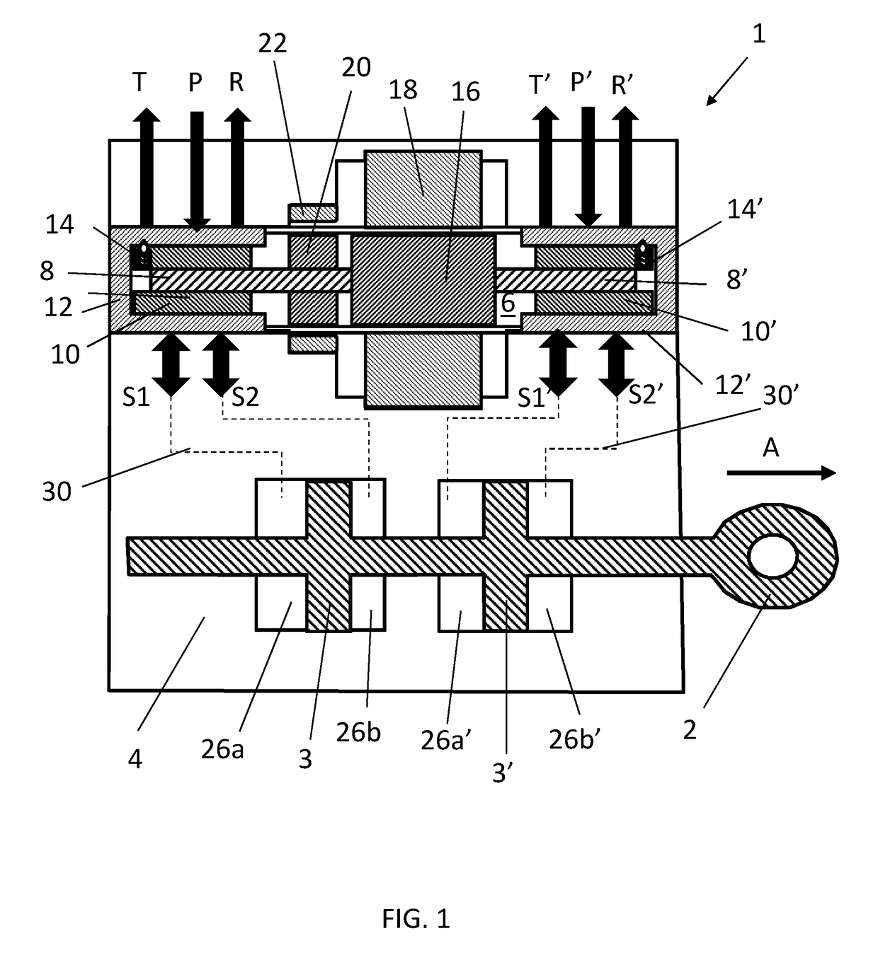
[0073]FIG. 1 shows a schematic cross-sectional view of a servo actuator 1 in accordance with a first example embodiment. A linear actuator arm 2 is located partially within an actuator housing 4. A spool 8 is located within a cylindrical cavity 6 and is connected to the left-hand side of a motor rotor 16 in FIG. 1. The motor rotor 16 is concentrically located within the cylindrical cavity 6. A motor stator 18 is connected to the inner surface of the actuator housing 4 which defines the cavity 6 and the stator 18 extends around the rotor 16. A sensor stator 22 is also connected to the inner surface of the actuator housing 4 via the motor stator 18. A sensor rotor 20 is connected to the spool 8.

[0074]A set of internal ports including inlet ports P, outlet ports T and control ports S1, S2 are formed in the inner surface of the actuator housing 4 which defines the extent of cavity 6 in the region of the left-hand spool 8. The internal ports are denoted by arrows in FIG. 1, and for clari...


PUM


Abstract

A servo actuator (1) comprises an actuator housing (4); an actuator member (2) located within the actuator housing (4) and at least one spool (8) located in a cavity (6) formed within the actuator housing (4). The housing (4) also comprises a first set of internal ports including an inlet port (P), an outlet port (T) and a pair of control ports (SI, S2), the inlet port (P) being arranged for connection to a first pressurised supply and a second set of internal ports comprising an inlet port (P′), an outlet port (T′) and a pair of control ports (SI′, S2′), the inlet port (P′) being arranged for connection to a second pressurised supply. In use, movement of the spool (8) alters the flow path of fluid through the first and second set of internal ports to control the movement of the actuator member (2).

Description

FIELD OF THE INVENTION[0001]The present invention concerns servo actuators, in particular servo actuators for use in aerospace applications. The invention also concerns an aircraft including such a servo actuator, a method of controlling the actuator of such a servo actuator, and controlling the movement of a flight control surface using such a servo actuator.BACKGROUND OF THE INVENTION[0002]Servo actuators are used in a wide variety of industries to produce a controlled movement in response to an input signal. Servo actuators are typically used in industries where precise control of the output motion is required. For example, in the aerospace industry, servo actuators may be used to move the control surfaces of an aircraft.[0003]A servo actuator includes a servo valve and an actuator. The servo valve alters the flow of a fluid through the servo actuator in order to control the position, velocity, acceleration or force generated by the actuator. Typical actuators include hydraulic o...

Claims


Application Information

Patent Timeline
IPC IPC(8): B64C27/64F15B13/04
CPCB64C27/64F15B13/0406F15B18/00F15B2211/8757F15B9/09F15B13/0402F15B13/043F15B2013/041
Inventor COLLINS, ANDREW JOHN
Owner BLAGDON ACTUATION RES
Why Eureka
Try Eureka