
Flying wing vertical take-off and landing aircraft

a vertical take-off and landing and flying wing technology, applied in vertical landing/take-off aircraft, aircraft power plants, vehicles, etc., can solve the problems of long range and endurance, high complexity and higher empty weight, and difficulty in folding the wings

Active Publication Date: 2018-10-04
SIKORSKY AIRCRAFT CORP
View PDF28 Cites 9 Cited by
  • Summary
  • Abstract
  • Description
  • Claims
  • Application Information

AI Technical Summary

Benefits of technology

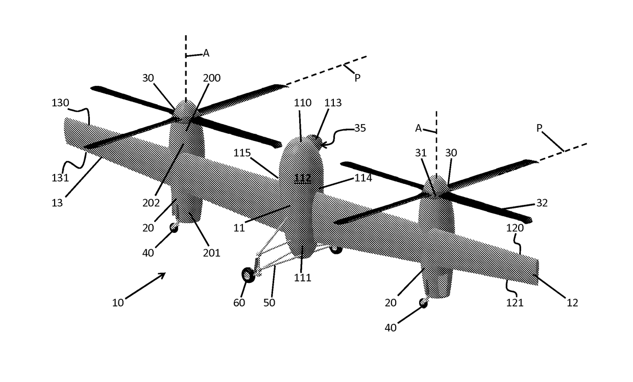
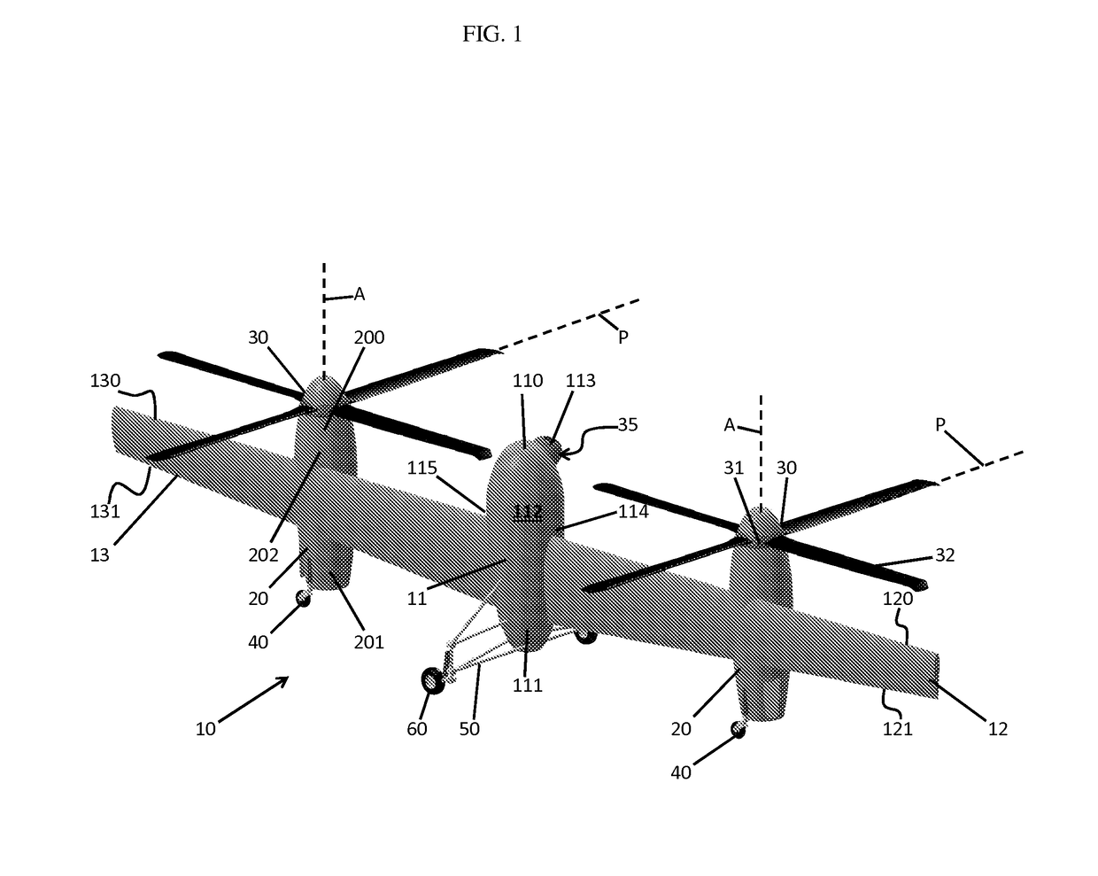
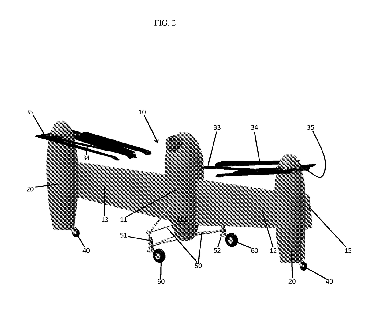
The invention provides a flying wing vertical take-off and landing (VTOL) aircraft with an empennageless-fuselage, empennagless-nacelle, and rigid rotor propeller that is fully cyclically controllable. The wings are high aspect ratio and have a forwardly swept trailing edge. Each wing also includes a hinge element and propellers with foldable rotor blades. The aircraft may also have additional landing gear elements and a truss element for added stability. The technical effects of this invention include improved efficiency, flexibility, and controllability of the VTOL aircraft.

Problems solved by technology

Aircraft missions often require VTOL capability that is combined with long range and endurance and can be very demanding.
Alternatively, some configurations include tilt-wing or tilt-rotor features and have VTOL capabilities, long range and endurance but pay a high penalty in terms of complexity and higher empty weight.
These tails make folding the wings difficult and adversely affect stowage capability of the aircraft.

Method used


Image

  • Flying wing vertical take-off and landing aircraft
  • Flying wing vertical take-off and landing aircraft
  • Flying wing vertical take-off and landing aircraft

Examples


Embodiment Construction

[0026]As will be described below, a flying wing VTOL aircraft is provided and includes a rigid rotor system having full cyclic control. This allows for a flying wing VTOL aircraft that takes off vertically, and has the ability to transition to wing borne flight by simply pitching the cyclic control forward to thereby cause the entire flying wing VTOL aircraft to rotate from a vertical to a horizontal orientation. By discarding any special rotation actuation mechanisms, typical penalties of higher weight and added complexity are removed. In addition, the active proprotors have the added advantage of permitting an elimination of ailerons and evlerons from the wings thus leading to further reductions in weight and cost. Meanwhile, the aircraft enhances shipboard operations by elimination of the horizontal tail, elevator and rudder from the overall configuration as this allows the wings to be folded and the aircraft to be stowed in a limited spatial environment.

[0027]With reference to F...


PUM


Abstract

A flying wing vertical take-off and landing (VTOL) aircraft is provided and includes an empennageless-fuselage from which foldable wings extend outwardly, an empennageless-nacelle supported on each of the wings and a rigid rotor propeller disposed on each empennageless-nacelle, each of the propellers being drivable to rotate about only a single rotational axis defined along a longitudinal axis of the corresponding empennageless-nacelle and being fully cyclically controllable.

Description

STATEMENT OF FEDERALLY SPONSORED RESEARCH AND DEVELOPMENT[0001]This invention was made with government support with the United States Government under Contract No. HR0011-14-C-0010. The government therefore has certain rights in this invention.BACKGROUND OF THE INVENTION[0002]The subject matter disclosed herein relates to a vertical take-off and landing (VTOL) aircraft and, more particularly, to a flying wing VTOL aircraft.[0003]Aircraft missions often require VTOL capability that is combined with long range and endurance and can be very demanding. Conventional configurations of such aircraft are designed primarily for efficient forward flight, for efficient vertical lift or a poor compromise solution. Alternatively, some configurations include tilt-wing or tilt-rotor features and have VTOL capabilities, long range and endurance but pay a high penalty in terms of complexity and higher empty weight. That is, a conventional tilt-wing aircraft carries an oversized fuselage for an inert...

Claims


Application Information

Patent Timeline
Patent Type & Authority Applications(United States)
IPC IPC(8): B64C29/02B64C25/04B64D31/06
CPCB64C29/02B64C25/04B64D31/06B64U50/12B64U30/293B64U60/50B64U10/20B64U80/70B64U30/12
Inventor SCOTT, MARK W.BUNTING, COLIN KEMATER
Owner SIKORSKY AIRCRAFT CORP
Learn More