
Strip light switch

a light switch and strip technology, applied in the field of strip light switch, can solve the problems of wasting components, affecting the service life of the lamp, so as to facilitate maintenance and repair work, save material and maintenance costs, and improve the effect of maintenance speed

Active Publication Date: 2018-10-04
DIPTRONICS MFG
View PDF0 Cites 3 Cited by
  • Summary
  • Abstract
  • Description
  • Claims
  • Application Information

AI Technical Summary

Benefits of technology

This invention is a strip light switch with a detachable terminal set and a conductive shrapnel. It includes an insulative housing with terminal grooves and positioning grooves, a terminal set with mating connection terminals, and a press device with a cylindrical press block and conducting plates. The press device is directly mounted in the insulative housing without bending the contact leg of the conducting plates, ensuring positive conduction of the terminal set and quick installation. The detachable mating connection terminals are stopped at the positioning groove edges and the abutment rods are in electrical contact with the third terminals, enhancing signal transmission stability and reliability. The invention avoids permanent deformation of the contact legs and saves material and maintenance costs. No sliding slider is used, avoids burr or fouling, and improves product yield.

Problems solved by technology

Of the contact legs D21 are bent with a large force, the contact legs D21 can be permanently deformed or get broken, leading to a contact failure with the terminal set B. When this problem occurs, the product become defective.
Because the contact legs D21 of the conducting plates D2 are 21 of the conducting plates D2 will be squeezed to deform by the terminal set B when the press device D is pressed, however, if the press device D is frequently pressed or pressed by a large force, the contact legs D21 of the conducting plates D2 can be permanently deformed or get broken, leading to a contact failure with the terminal set B. Further, because the conducting plates D2 are mounted in the press device D, the whole press device D must be replaced if any of the conducting plates D2 gets broken, complicating the repair work, wasting the component part and increasing the repair costs.

Method used


Image

  • Strip light switch
  • Strip light switch
  • Strip light switch

Examples


Embodiment Construction

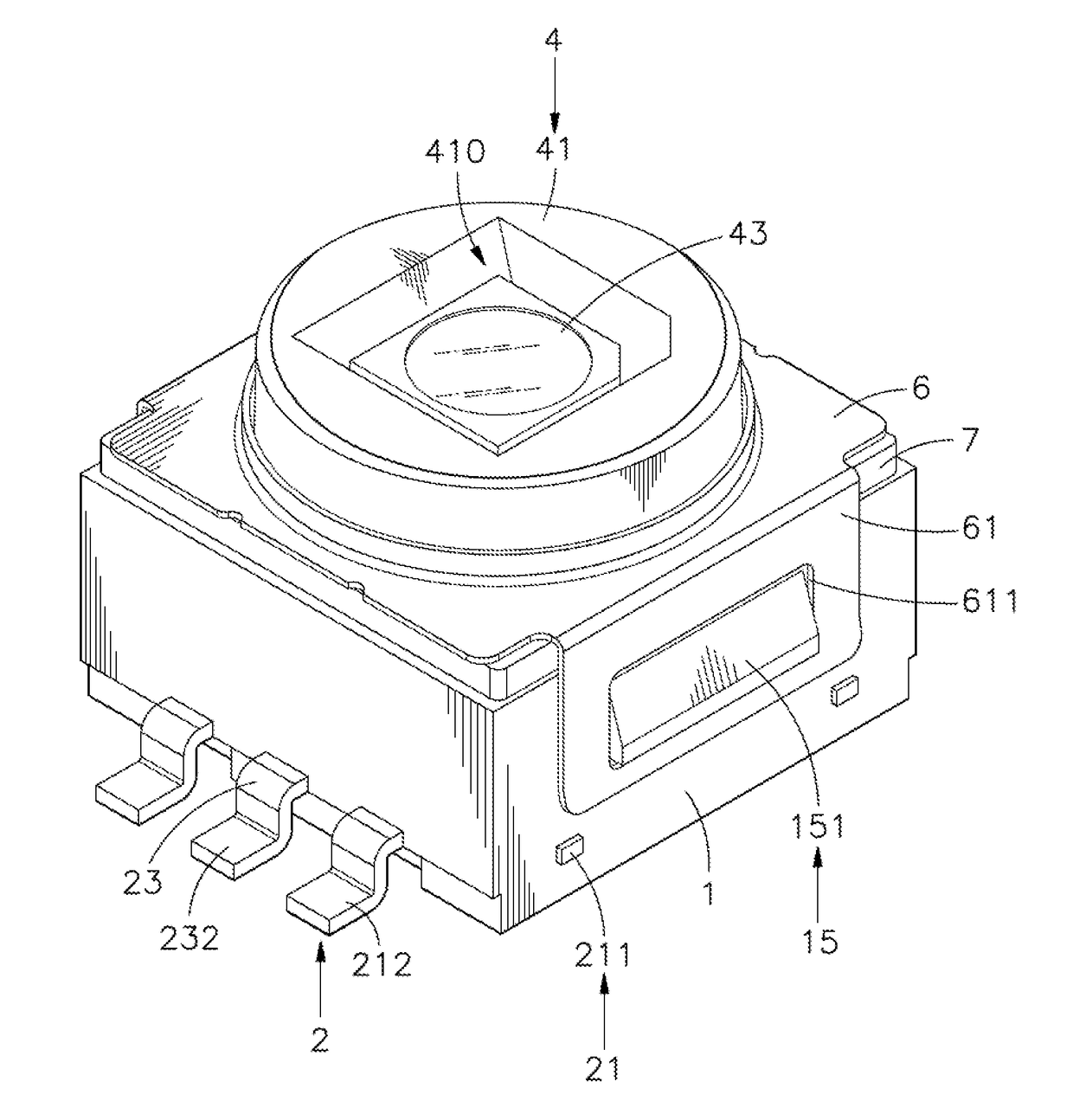
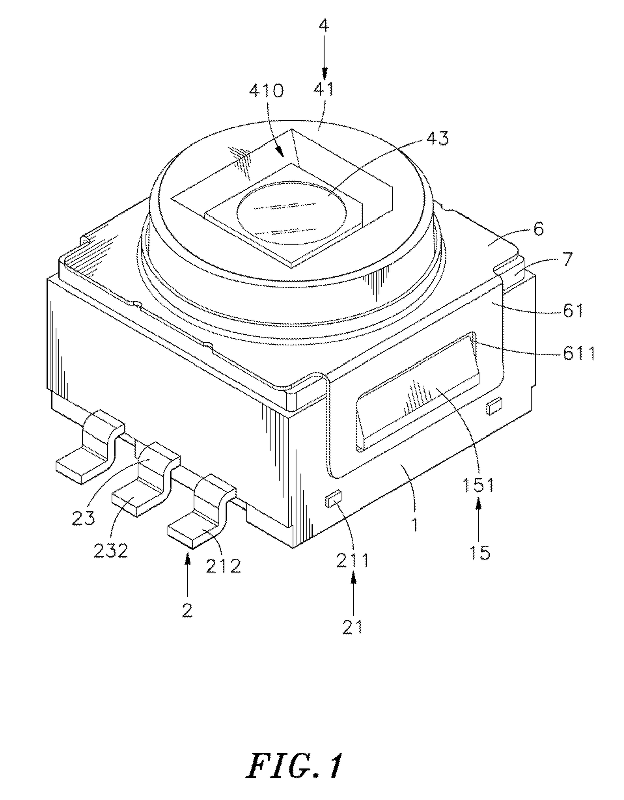
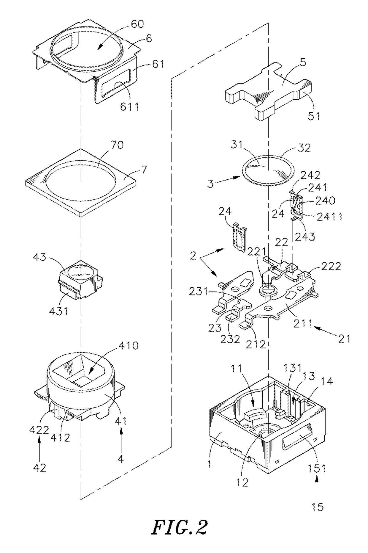
[0019]Referring to FIGS. 1-3, a strip light switch in accordance with the present invention is shown. The strip light switch comprises an insulative housing 1, a terminal set 2, a conductive shrapnel 3, a press device 4, an elastomer 5, a cover 6 and a gasket 7.

[0020]The insulative housing 1 comprises an accommodation chamber 11, a plurality of terminal grooves 12 located in an inner bottom side of the accommodation chamber 11, two positioning grooves 13 vertically disposed in the accommodation chamber 11 at two opposite sides, a recessed stop edge 131 located at a top open end of the each positioning groove 13, at least one position-limiting groove 14 symmetrically disposed at two opposite lateral sides of the each positioning groove 13, and a male retaining structure 15 comprises at least one retaining block 151 symmetrically located at the outer peripheral wall of the insulative housing 1 at two opposite sides.

[0021]The terminal set 2 comprises at least one first terminal 21, at ...


PUM


Abstract

A strip light switch includes an insulative housing with terminal grooves and positioning grooves defined in an accommodation chamber therein, a terminal set including at least one first terminal, at least one second terminal and multiple third terminals mounted in the terminal grooves and multiple mating connection terminals detachably mounted in the positioning grooves in a replaceable manner for conduction with the third terminals, a conductive shrapnel mounted in the accommodation chamber, and a press device including a cylindrical press block supported on the conductive shrapnel pressable by a user to force the conductive shrapnel in conducting the first and second terminals, conducting plates mounted in the cylindrical press block and disposed in contact with the conducting plates of the mating connection terminal and a light-emitting component mounted in the cylindrical press block for electrical contact with the conducting plates.

Description

BACKGROUND OF THE INVENTION[0001]This application claims the priority benefit of Taiwan patent application number 106204412, filed on Mar. 29, 2017.1. Field of the Invention[0002]The present invention relates to switch technology and more particularly, to a strip light switch, which has the mating connection terminals of the terminal set thereof respectively detachably mounted in respective positioning grooves in the insulative housing thereof, so that the mating connection terminals can be removed from the positioning grooves for a replacement if they are permanently deformed or get broken, facilitating maintenance and repair works, improving maintenance speed, and saving material and maintenance costs.2. Description of the Related Art[0003]FIGS. 6 and 7 illustrate a strip light switch according to the prior art. According to this design, the strip light switch comprises a housing A, a terminal set B, a conductive shrapnel C, a press device D and a light-emitting component E. The h...

Claims


Application Information

Patent Timeline
Patent Type & Authority Applications(United States)
IPC IPC(8): F21V23/04H01H13/14F21V21/005
CPCH01H2013/525F21V23/04H01H13/14F21V21/005H01H13/023H01H13/52H01H2203/038H01H2227/026
Inventor LIN, SHI-CHI
Owner DIPTRONICS MFG
Learn More