Coil device
a coil device and coil technology, applied in the direction of inductances, inductances with magnetic cores, basic electric elements, etc., can solve the problems of low profile and the structure of patent document 1 has a problem of lowering inductance, and achieve the effect of further improving the valu
Inactive Publication Date: 2018-10-04
TDK CORPARATION
View PDF3 Cites 0 Cited by
- Summary
- Abstract
- Description
- Claims
- Application Information
AI Technical Summary
Benefits of technology
The present invention is a coil device that has a large inductance, can reduce interference between two objects, and has a low profile. Its technical effects are to improve the performance of electronic devices that use coils for data transfer and to reduce the size of such devices.
Problems solved by technology
Since a primary wire and a secondary wire are wound around a winding portion separately from each other in a coaxial center extended line, however, a height of the winding portion in its axial direction needs to be maintained, and there is thereby a problem of low profile.
In addition, the structure of Patent Document 1 has a problem of lowering of inductance.
Method used
View moreImage
Smart ImageViewing Examples
Examples
example 1
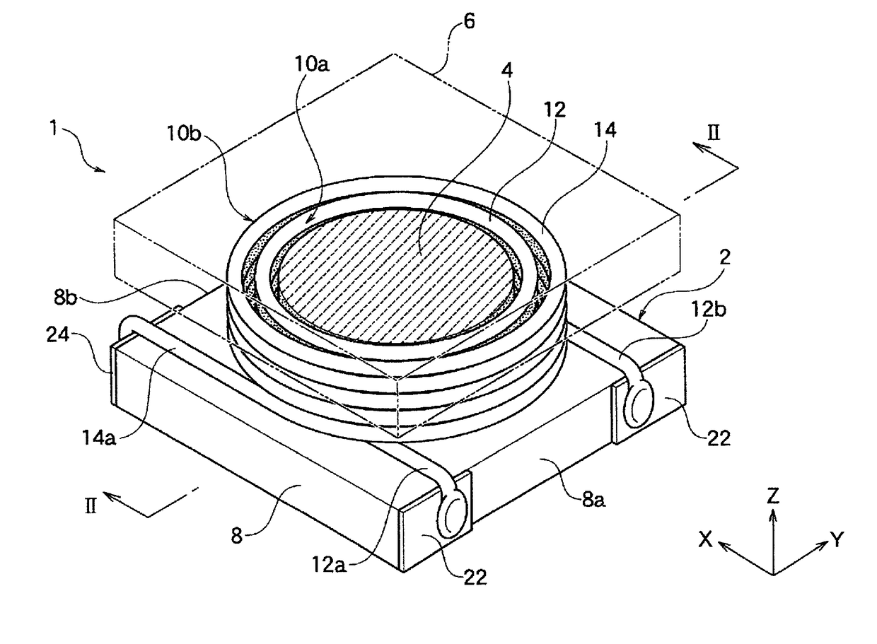
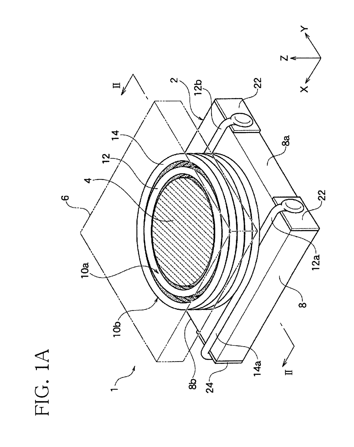
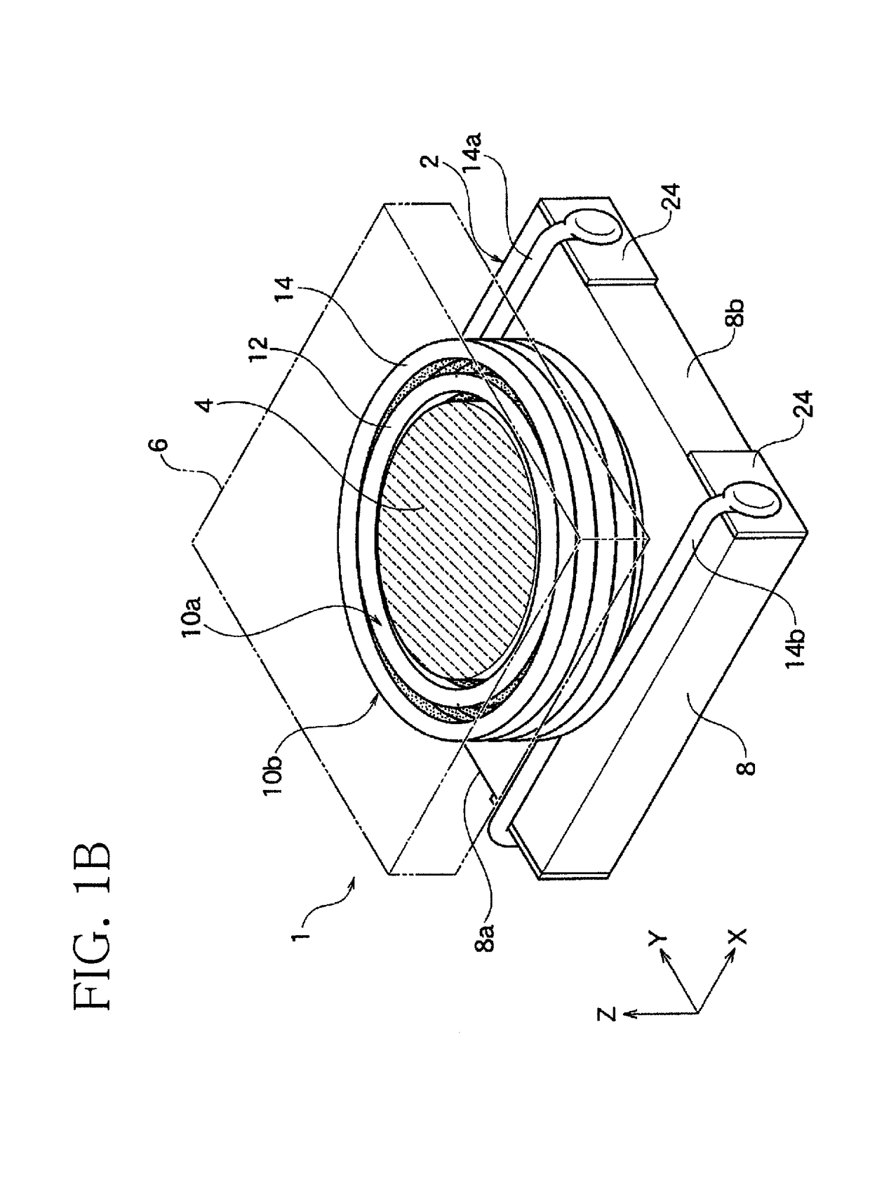
[0045]A coil device shown in FIG. 1A to FIG. 2 was manufactured. The thickness of an intermediate insulating layer 20 was 150 μm. This coil device was measured with respect to coupling coefficient “k” by changing frequency. A curve of ex. 1 in FIG. 3 shows the measurement results.
Login to View More PUM
| Property | Measurement | Unit |
|---|---|---|
| height | aaaaa | aaaaa |
| height | aaaaa | aaaaa |
| width | aaaaa | aaaaa |
Abstract
A coil device includes a core, an inner coil portion, an outer coil portion, and an intermediate resin layer. The core includes a winding portion and a flange positioned at an end of the winding portion in an axial direction. The inner coil portion is constituted by winding a first wire around the winding portion. The outer coil portion is constituted by winding a second wire outside the inner coil portion. The intermediate resin layer exists between the inner coil portion and the outer coil portion.
Description
BACKGROUND OF THE INVENTION1. Field of the Invention[0001]The present invention relates to a coil device capable of being used as a coupled inductor (coupling inductor), for example.2. Description of the Related Art[0002]Maintenance of L value and reduction of coupling coefficient are required to be adjusted in, for example, surface-mount coil devices. As shown in Patent Document 1 below, for example, coupling coefficient can be reduced by winding a primary wire and a secondary wire disposed separately from each other in a coaxial center extended line.[0003]Since a primary wire and a secondary wire are wound around a winding portion separately from each other in a coaxial center extended line, however, a height of the winding portion in its axial direction needs to be maintained, and there is thereby a problem of low profile. In addition, the structure of Patent Document 1 has a problem of lowering of inductance.[0004]Patent Document 1: JP 2001-338819 ASUMMARY OF THE INVENTION[0005]...
Claims
Login to View More Application Information
Patent Timeline
 Patent Type & Authority Applications(United States)
IPC IPC(8): H01F17/04H01F27/24H01F27/28H01F27/00H01F27/29
CPCH01F17/045H01F27/24H01F27/2823H01F27/006H01F27/292H01F27/2828
Inventor KOBAYASHI, TSUTOMUTOMONARI, TOSHIOFUJIWARA, KIYOFUMIITO, EMI
Owner TDK CORPARATION
Features
- R&D
- Intellectual Property
- Life Sciences
- Materials
- Tech Scout
- Unparalleled Data Quality
- Higher Quality Content
- 60% Fewer Hallucinations
Learn More Browse by: Latest US Patents, China's latest patents, Technical Efficacy Thesaurus, Application Domain, Technology Topic, Popular Technical Reports.
© 2025 PatSnap. All rights reserved.Legal|Privacy policy|Modern Slavery Act Transparency Statement|Sitemap|About US| Contact US: help@patsnap.com


