Image generation device and imaging device

a technology of image generation and image, applied in the direction of radio frequency controlled devices, color signal processing circuits, instruments, etc., can solve the problems of color image resolution decline after demosaicing and artifacts referred to as false colors

Active Publication Date: 2018-10-04
PANASONIC INTELLECTUAL PROPERTY MANAGEMENT CO LTD
View PDF3 Cites 1 Cited by
  • Summary
  • Abstract
  • Description
  • Claims
  • Application Information

AI Technical Summary

Benefits of technology

The present patent provides a system, method, computer program, and computer-readable recording medium for generating an appropriate image while suppressing a decline in resolution. Additionally, the patent provides an imaging device for generating an appropriate image. The technical effects of the patent include improved image quality, reduced image resolution loss, improved image processing speed, and improved image data management. These improvements can lead to better overall quality of the processed images and reduced costs associated with image processing.

Problems solved by technology

Therefore, the resolution of the color image subsequent to demosaicing may decline and artifacts referred to as false color may occur.

Method used


Image

  • Image generation device and imaging device
  • Image generation device and imaging device
  • Image generation device and imaging device

Examples


embodiment 1

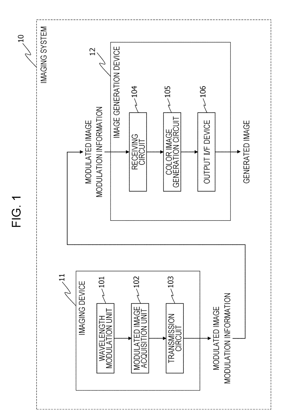
[0050]FIG. 1 depicts a configuration of an imaging system 10 according to the present embodiment. The imaging system 10 is provided with an imaging device 11 and an image generation device 12.

[0051]The imaging device 11 has a wavelength modulation unit 101, a modulated image acquisition unit 102, and a transmission circuit 103. Meanwhile, the image generation device 12 has a receiving circuit 104, a color image generation circuit 105, and an output I / F (interface) device 106. The imaging device 11 and the image generation device 12 may be integrated. It goes without saying that, in a case where the imaging device 11 and the image generation device 12 are integrated, the transmission circuit 103 and the receiving circuit 104 can be omitted.

(Imaging Device 11)

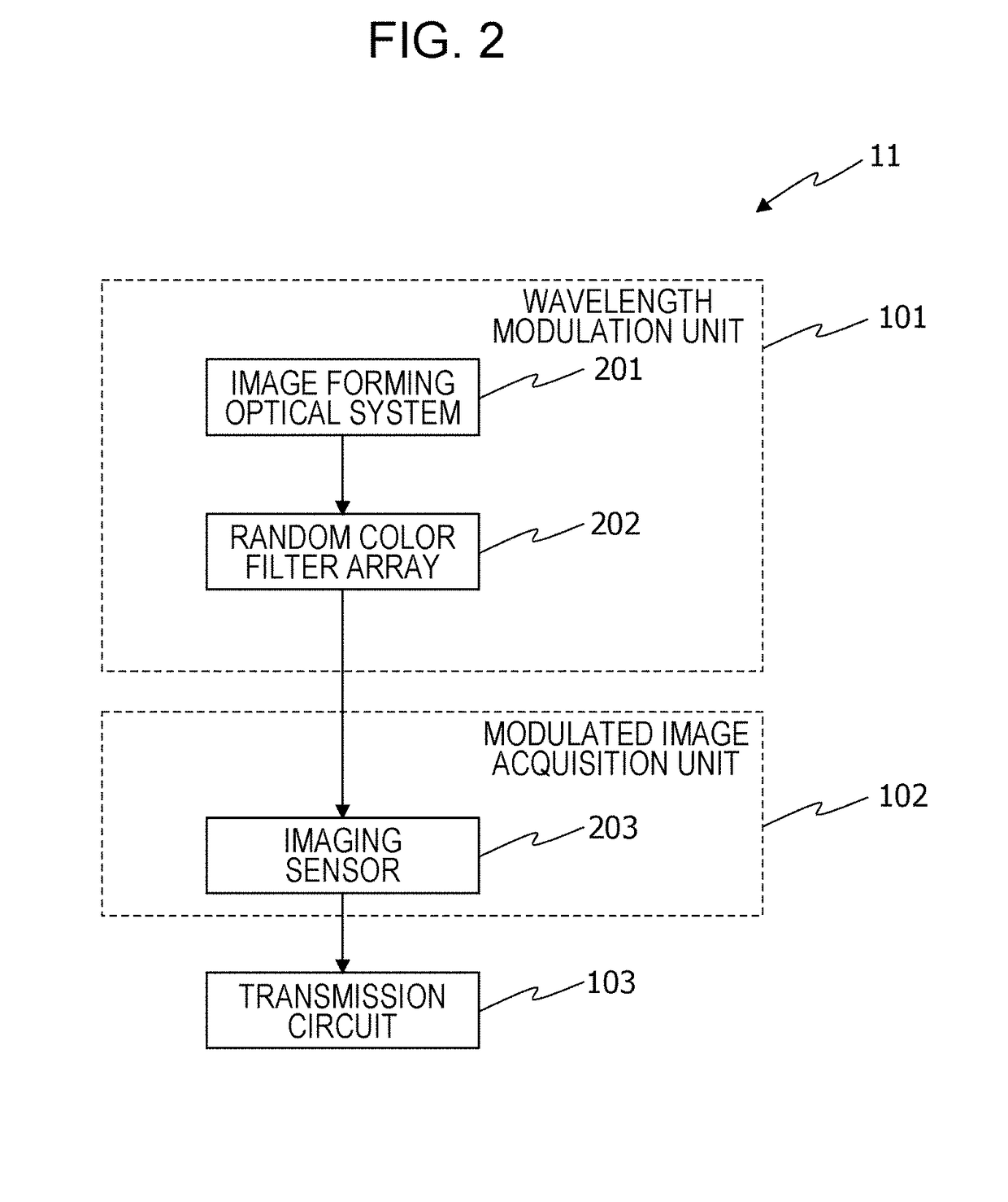
[0052]First, the imaging device 11 will be described with reference to FIG. 2.

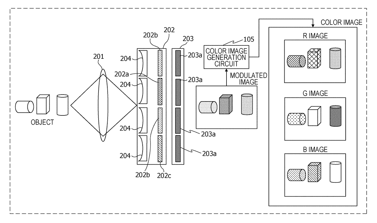
[0053]FIG. 2 depicts details of a configuration of the wavelength modulation unit 101 and the modulated image acquisition unit 102.

[0054]As depicted in...

embodiment 2

[0130]FIG. 17 depicts a configuration of the imaging system 10 according to the present embodiment. From among the constituent elements of the imaging system 10 according to the present embodiment, constituent elements that are the same as those of the imaging system 10 given in embodiment 1 are denoted in FIG. 17 by the same reference numbers as in FIG. 1, and descriptions thereof are omitted here as appropriate. The imaging system 10 according to the present embodiment is provided with a multi-band image generation circuit 107, instead of the color image generation circuit 105 given in embodiment 1, in the image generation device 12. This imaging system 10 can generate a multi-band image that is not restricted to an RGB color image of the three primary colors. A multi-band image is an image expressed by a signal in which the wavelength bands of light are divided into four or more regions. Those wavelength bands are not restricted to visible light and may be wavelength bands such a...


PUM


Abstract

An imaging system serving as an image generation device is provided with: a random color filter array that has a plurality of concave lenses and a plurality of color filters having different transmission characteristics; a photodiode that receives light that has passed through the random color filter array; an AD converter that converts the light received by the photodiode into digital data; and a color image generation circuit that generates an image using the digital data and modulation information of the random color filter array, in which the plurality of concave lenses are located between the plurality of color filters and the photodiode, or the plurality of color filters are located between the plurality of concave lenses and the photodiode.

Description

BACKGROUND1. Technical Field[0001]The present disclosure relates to an image generation device and the like in which a compressed sensing technique is used.2. Description of the Related Art[0002]In order to capture a color image, it is necessary to acquire information regarding the three different wavelength regions of red (R), green (G), and blue (B) that correspond to the three primary colors of light. There are color imaging devices that acquire information regarding R, G, and B using three image sensors. However, many color imaging devices are equipped with only one image sensor in order to reduce size and cost. Therefore, many color imaging devices acquire information regarding R, G, and B using one image sensor.[0003]There is a conventionally known method in which information regarding one wavelength region from among R, G, and B is acquired for each pixel, and information regarding the three wavelength regions of R, G, and B is acquired for each pixel by carrying out processi...

Claims


Application Information

Patent Timeline
IPC IPC(8): H01L27/146H04N5/225H04N9/65H04N9/67H04N9/04G06T3/40
CPCH01L27/14627H01L27/14621H01L27/14645H04N5/2254H04N9/65H04N9/67H04N9/045G06T3/4015H04N2209/045H04N23/55H04N25/703H04N25/133H04N25/134H04N23/10H04N25/702
Inventor SATOWATANABE, HISASHIAZUMA, TAKEONOBORI, KUNIOWAKAI, NOBUHIKOANDO, TAKAMASA
Owner PANASONIC INTELLECTUAL PROPERTY MANAGEMENT CO LTD
Why Eureka
Try Eureka