Electronic Switch for Electronic Fuse

a technology of electronic fuse and electronic switch, which is applied in the direction of logic circuit coupling/interface arrangement, logic circuit coupling arrangement, multiple input and output pulse circuit, etc., and can solve problems such as insufficient drive circuits

Active Publication Date: 2018-10-04
INFINEON TECH AG
View PDF0 Cites 20 Cited by
  • Summary
  • Abstract
  • Description
  • Claims
  • Application Information

AI Technical Summary

Problems solved by technology

However, the piece of wire is designed to heat up and melt or vaporize when the current passing through the fuse exceeds the nominal current for a specific time.
However, at least in some electronic circuit breakers (electronic fuses or e-fuses)

Method used


Image

  • Electronic Switch for Electronic Fuse
  • Electronic Switch for Electronic Fuse
  • Electronic Switch for Electronic Fuse

Examples


Embodiment Construction

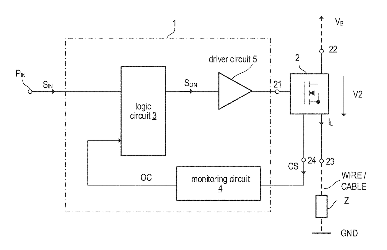
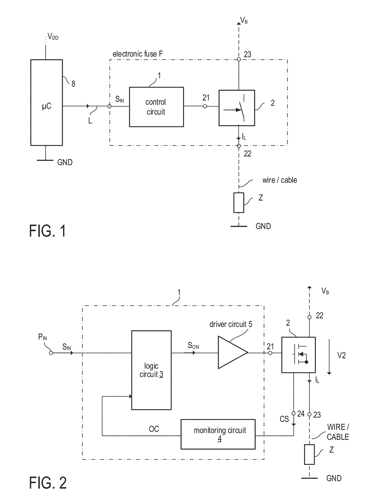
[0029]FIG. 1 illustrates one example of an electronic circuit, which may be operated as an electronic fuse. Therefore the electronic circuit is further referred to as electronic fuse circuit F. In accordance with the present example, an electronic fuse circuit includes an electronic switch 2 with a control node 21 and a load current path between a first load node 22 and a second load node 23. The electronic circuit further includes a control circuit 1 coupled to the control node 21 of the electronic switch 2 and configured to drive the electronic switch 2. The electronic fuse circuit F with electronic switch 2 and control circuit 1 may be monolithically integrated on one semiconductor die (chip) or may be integrated in two semiconductor dies that are arranged in one integrated circuit package. The electronic fuse circuit F is configured to drive a load Z (the wires connecting the load are illustrated in dashed lines in FIG. 1) that can be connected in series with the load current pa...


PUM


Abstract

In accordance with one example, the electronic switch has a load current path operably coupled to a load via a wire; the electronic switch is configured to connect or disconnect a load current supply node and the load via the wire dependent on a drive signal. Further, the electronic fuse circuit includes a monitoring circuit configured to receive a current sense signal representing the load current passing through the wire and to determine a first protection signal based on the current sense signal and at least one wire parameter. The first protection signal is indicative of whether to disconnect the load current supply node from the load. Moreover, the electronic fuse circuit includes a logic circuit configured to receive at least one selection signal and to set the at least one wire parameter based on the at least one selection signal.

Description

[0001]This application claims the benefit of German Application No. 102017106896.1, filed on Mar. 30, 2017, which application is hereby incorporated herein by reference in its entirety.TECHNICAL FIELD[0002]This disclosure in general relates to aspects of an electronic switching and protection circuit, and more particularly to a drive circuit for an electronic switch.BACKGROUND[0003]Almost every electric installation (e.g. in an automobile, in a house, electric subsystems of larger installations) include one of more fuses to provide an over-current protection. Standard fuses include piece of wire, which provides a low-ohmic current path in case the current passing through the fuse is below a nominal current. However, the piece of wire is designed to heat up and melt or vaporize when the current passing through the fuse exceeds the nominal current for a specific time. Once triggered a fuse has to be replaced by a new one.[0004]Fuses are increasingly replaced by circuit breakers. A cir...

Claims


Application Information

Patent Timeline
IPC IPC(8): H02H1/00H02H3/08H03K5/24
CPCH02H1/0092H02H1/0007H02H3/085H03K5/24H02H3/08H03K19/017545H03K17/0822H02H3/006H02H3/10H02H5/04H02H3/04H02H3/046
Inventor DJELASSI-TSCHECK, CHRISTIANILLING, ROBERTLAMACCHIA, COSIMOTRIPOLT, MARIO
Owner INFINEON TECH AG
Why Eureka
Try Eureka