Control device for internal combustion engine

a control device and internal combustion engine technology, applied in the direction of electric control, machines/engines, fuel injecting pumps, etc., can solve the problems of difficult valves, keen difficulties in the abnormality of pressure increase control valves in the pressure increasing device,

Active Publication Date: 2018-10-11
TOYOTA JIDOSHA KK
View PDF0 Cites 3 Cited by
  • Summary
  • Abstract
  • Description
  • Claims
  • Application Information

AI Technical Summary

Benefits of technology

[0005]Incidentally, by detecting the waveform of the fuel pressure measured in the fuel injection valve, whether the cause of the abnormality m fuel injection is the pressure increasing device or the fuel injection valve can he specified. However, determining whether or not there is an abnormality in a pressure increase control valve in the pressure increasing device has keen difficult. For example, when the pressure increasing device cannot increase the fuel pressure due to an abnormality in the pressure increasing piston and when the pressure increasing device cannot increase the fuel pressure due to an abnormality in the pressure increase control valve, there is a possibility that the waveform of the fuel pressure measured in the fuel injection valve will have a similar shape. In the above cases, specifying whether or not there is an abnormality in the pressure increase control valve by detecting the waveform of the fuel pressure measured at the fuel injection, valve has been difficult.

Problems solved by technology

However, determining whether or not there is an abnormality in a pressure increase control valve in the pressure increasing device has keen difficult.
In the above cases, specifying whether or not there is an abnormality in the pressure increase control valve by detecting the waveform of the fuel pressure measured at the fuel injection, valve has been difficult.

Method used


Image

  • Control device for internal combustion engine
  • Control device for internal combustion engine
  • Control device for internal combustion engine

Examples


first embodiment

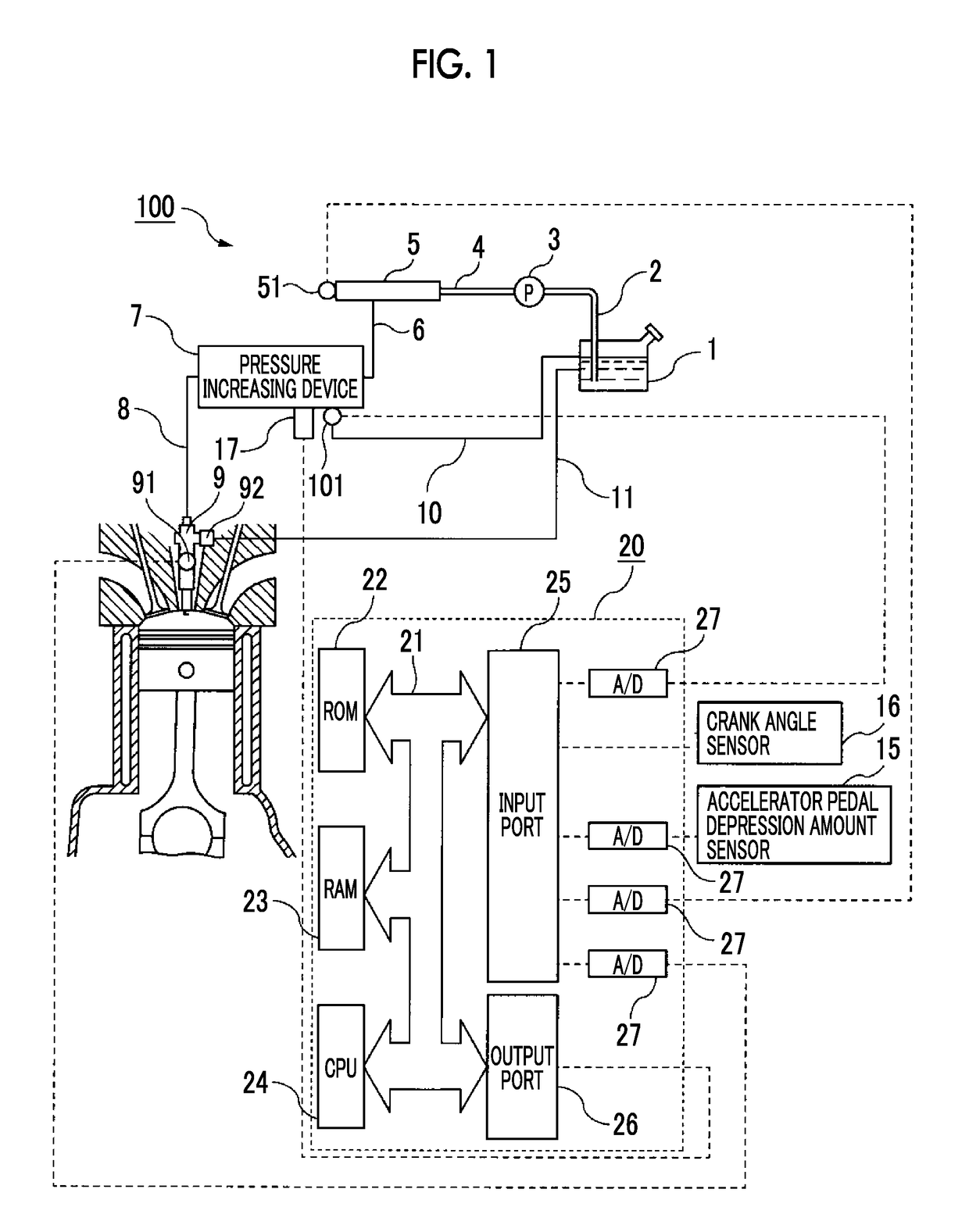
[0023]FIG. 1 is a schematic configuration diagram of an internal combustion engine 100 according to a first embodiment of the present disclosure and an electronic control unit 20 that controls the internal combustion engine 100.

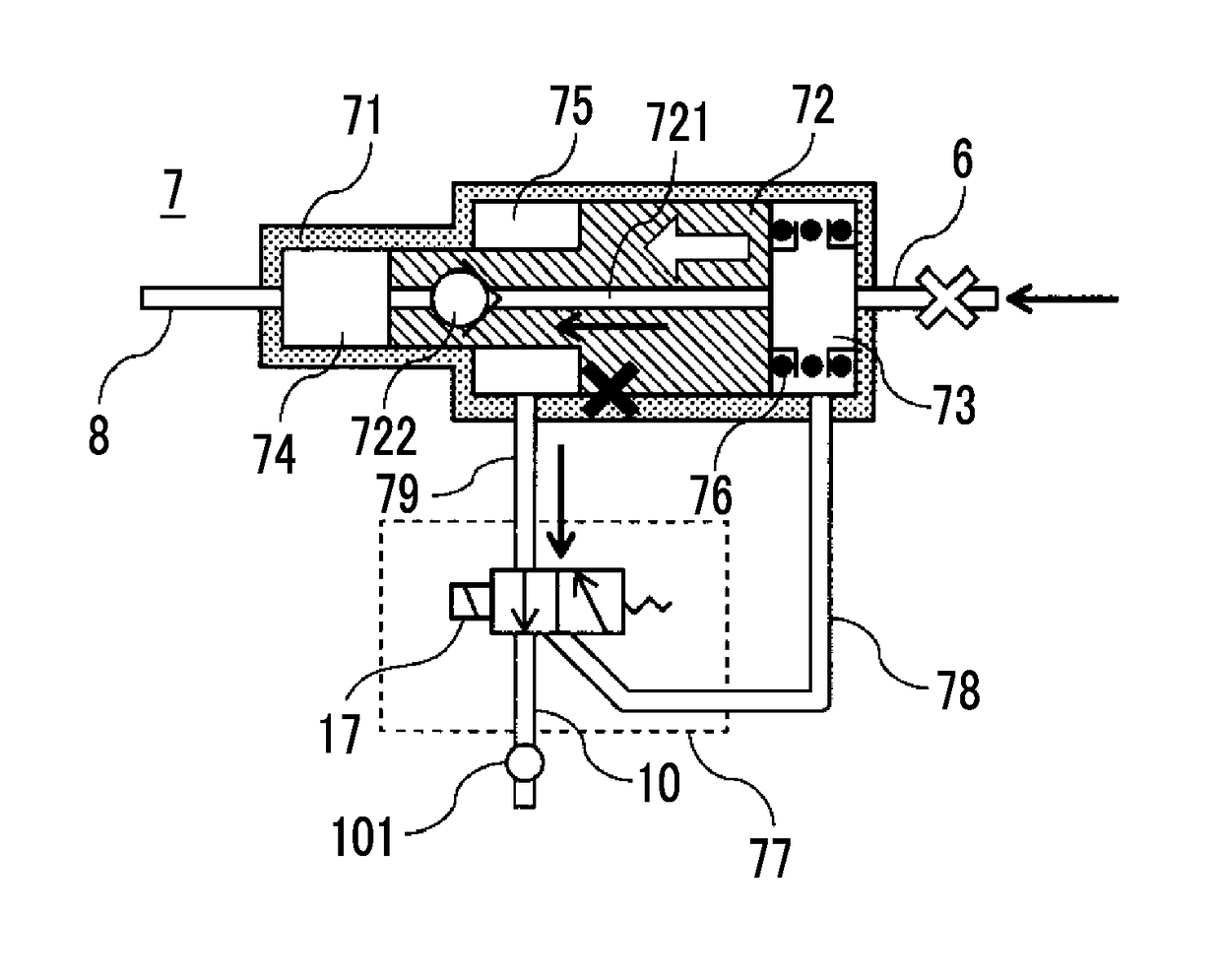
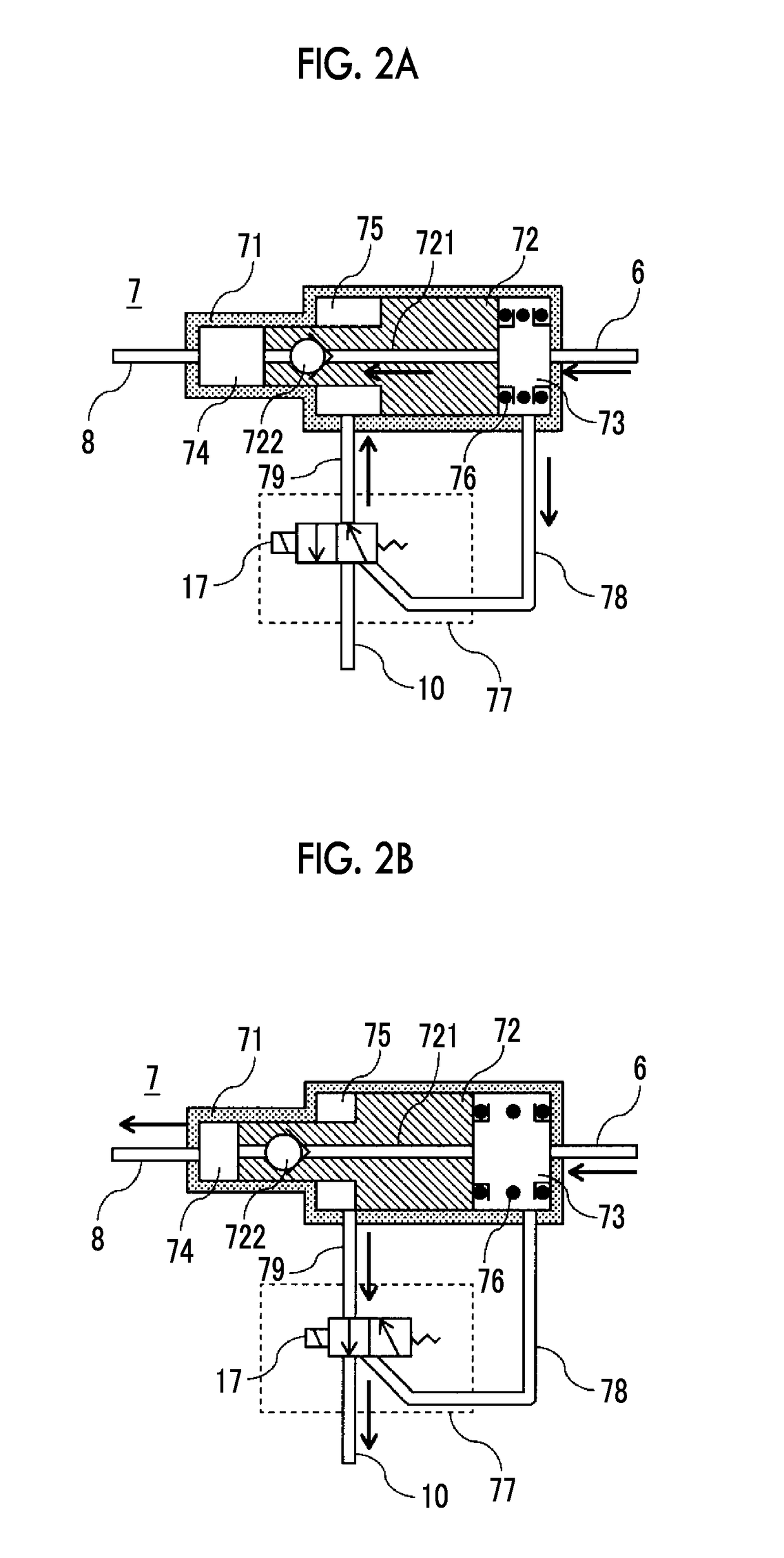
[0024]The internal combustion engine 100 according to the present embodiment includes a fuel tank 1, a pump suction passage 2, a supply pump 3, a pump discharge passage 4, a common rail 5, a supply passage 6, a pressure increasing device 7; an injection passage 8, an injector 9, a return passage 10 and a relief passage 11.

[0025]The fuel tank 1 stores fuel supplied from the outside at atmospheric pressure. The fuel stored in the fuel tank 1 is sucked up by the supply pump 3 through the pump suction passage 2.

[0026]The supply pump 3 sucks up the fuel stored in the fuel tank 1, and increases the fuel pressure. The fuel having a pressure that has been increased by the supply pump 3 is supplied to the common rail 5 through the pump discharge passage 4. The amount ...

second embodiment

[0111]A routine for detecting an abnormality in the three-way valve 77 in a second embodiment of the present disclosure will be described. The routine of the second embodiment of the present disclosure includes a routine relevant to the fuel injection described in FIG. 6, a routine relevant to the fuel injection setting described in FIG. 10, and a routine relevant to the abnormality detection described in FIG. 11.

[0112]In the first embodiment the electronic control unit 20 determines whether or not there is an abnormality in the fuel system in step S125 in FIG. 9 and then determines whether or not there is an abnormality in the three-way valve 77 in step S133. On the other hand, the second embodiment is different from the first embodiment in that the electronic control unit 20 determines whether or not there is an abnormality in the fuel system after determining whether or not there is an abnormality in the three-way valve 77 in step S133 in FIG. 11. In the first embodiment, by dete...


PUM


Abstract

A control device for an internal combustion engine includes a feel tank, a high pressure feel passage, a pressure increasing device, a switching device, a low pressure fuel passage, a temperature sensor, a fuel injector, and an electronic control unit. The electronic control unit is configured to determine that there is an abnormality in the switching device when a temperature measured by the temperature sensor when the pressure increase signal is output is not higher than a temperature measured by the temperature sensor when the pressure increase signal is not output. The electronic control unit is configured to stop fuel pressure increase by the pressure increasing device by stopping an output of the pressure increase signal regardless of the engine operation state when the electronic control unit determines that there is the abnormality in the switching device.

Description

CROSS -REFERENCE TO RELATED APPLICATIONS[0001]This application claims priority to Japanese Patent Application No. 2017-078404 filed on Apr. 11, 2017, which is incorporated herein by reference in its entirety including the specification, drawings and abstract.BACKGROUND1. Technical Field[0002]The present disclosure relates to a control device for m internal combustion engine.[0003]2. Description of Related Art[0004]An internal combustion engine is known in which fuel which is supplied from a common rail, and a pressure of which is further increased by a pressure increasing device, is injected through a fuel injection valve. As the pressure increasing device described above, a pressure increasing device having a pressure increasing piston for supplying fuel from the pressure increasing device and a pressure increase control valve for controlling the pressure of fuel acting on the pressure increasing piston is known. Specifying whether the cause of an abnormality is the pressure increa...

Claims


Application Information

Patent Timeline
Patent Type & Authority Applications(United States)
IPC IPC(8): F02D41/22F02M37/00F02M37/04F02D41/38
CPCF02D41/221F02M37/0052F02M37/04F02D41/3845F02D2200/0606F02D2200/0602F02D2041/224F02D41/3836F02M57/025F02M59/105F02M47/00
Inventor HIRANO, TAKAHIRO
Owner TOYOTA JIDOSHA KK
Why Eureka
Try Eureka