Pipe condition detection device, pipe condition detection method, computer-readable recording medium, and pipe condition detection system

a technology of condition detection and pipe, which is applied in the direction of fluid leakage detection, fluid tightness measurement, instruments, etc., can solve the problems of post-maintenance activity and requires prompt action

Inactive Publication Date: 2018-10-11
NEC CORP
View PDF2 Cites 5 Cited by
  • Summary
  • Abstract
  • Description
  • Claims
  • Application Information

AI Technical Summary

Benefits of technology

[0013]According to the present invention, conditions of deterioration or a defect inside and outside a pipe can be estimated.

Problems solved by technology

However, leakage inspection by audition is posterior maintenance activity, and thus requires prompt action such as repair and replacement after detection.

Method used


Image

  • Pipe condition detection device, pipe condition detection method, computer-readable recording medium, and pipe condition detection system
  • Pipe condition detection device, pipe condition detection method, computer-readable recording medium, and pipe condition detection system
  • Pipe condition detection device, pipe condition detection method, computer-readable recording medium, and pipe condition detection system

Examples


first example embodiment

[0024]Hereinafter, an example embodiment of the present invention is described with reference to the drawings. The example embodiment of the present invention is described by citing, as an example, a system for detecting a pipe condition of a water pipe by using a vibration sensor and a pressure sensor installed at the water pipe. Note that the present invention is not limited to waterworks, but can be applied to a pipe for carrying gas, air, or the like. Here, the “pipe condition” in the present example embodiment represents a condition in which a pipe becomes thin by being worn out, for example. The “pipe condition” is not limited to the condition mentioned on the left, and may be a condition in which deposits accumulate on an inner wall of a pipe and an inner diameter of the pipe is thereby reduced, a condition in which an outer wall of a pipe is worn out due to corrosion or the like, a condition in which deposits adhere to an outer wall of a pipe and the pipe becomes thick, a co...

operation example

[0054]An example in which the first example embodiment is applied is described with reference to FIG. 7. FIG. 7 is a diagram illustrating, as an example, a pipe condition detected by the pipe condition detection device. In FIG. 7, the vertical axis represents a pipe wall parameter of the pipe, and the horizontal axis represents an inner diameter of the pipe. The dot located at the center of the drawing indicates an initial value. The dotted line in FIG. 7 indicates a normal range as an example. The normal range is not particularly limited, and may be appropriately set by a user. When a calculated inner diameter of the pipe and a calculated pipe wall parameter of the pipe are within the normal range, the control unit 203 determines that the pipe condition is normal. Specific determination results are exemplified below.

[0055]In the case of the example 1, the control unit 203 determines that a condition of the pipe is abnormal because of deviation from the normal range. Further, since ...

second example embodiment

[0064]A configuration of a second example embodiment is described with reference to FIG. 8. FIG. 8 is a diagram illustrating the configuration of a pipe condition detection system 2000 according to the second example embodiment.

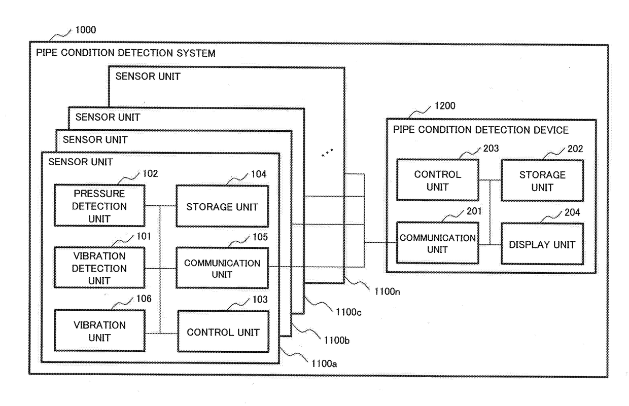
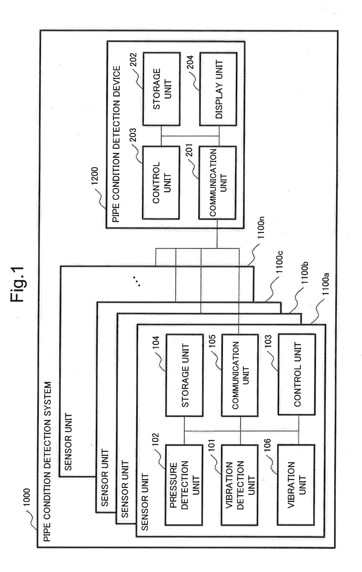
[0065]The pipe condition detection system 2000 includes a plurality of sensor units 2100a to 2100n and a pipe condition detection device 1200.

[0066]The sensor unit 2100 includes a vibration detection unit 101, a pressure detection unit 102, a control unit 103, a storage unit 104, a communication unit 105, a vibration unit 106, and a temperature detection unit 107. The sensor unit 2100 is installed at a sprinkler head of a pipe. Note that the sensor unit 2100 differs from the sensor unit 1100 according to the first example embodiment only in including the temperature detection unit 107, and thus, the descriptions other than the temperature detection unit 107 are omitted.

[0067]The temperature detection unit 107 detects a temperature of a pipe material. The temp...


PUM


Abstract

There are circumstances in which estimation of a pipe condition is desired as needs of water utility companies, and thus, an object of the present invention is to provide a technique that can estimate conditions of deterioration or a defect inside and outside a pipe.In order to solve the problem, a pipe condition detection system according to the present invention includes: a sensor unit that detects vibration data and pressure data from a pipe or fluid in the pipe; and a determination unit that determines conditions inside and outside the pipe, based on the vibration data and the pressure data acquired by the sensor unit.

Description

TECHNICAL FIELD[0001]The present invention relates to a pipe condition detection device, a pipe condition detection method, a computer-readable recording medium, and a pipe condition detection system.BACKGROUND ART[0002]Due to progress in IT and network technology supported by digitalization, an information amount handled and accumulated by persons and electronic devices is steadily increasing. In order for human society getting distracted with a large amount of information to establish safe and secure society, it is regarded as important that accurate data of an event are acquired from a sensor as an input device, accurately analyzed, determined, and processed, and are recognized as useful information by a person.[0003]Facilities such as water supply and sewer networks and high pressure chemical pipelines for gas, oil, and the like are constructed, and function as foundations for affluent society. As inspection of fluid leakage due to deterioration and destruction of pipes such as ...

Claims


Application Information

Patent Timeline
Patent Type & Authority Applications(United States)
IPC IPC(8): G01M5/00G01H3/06G01H3/14G01M3/18
CPCG01M5/0058G01H3/06G01H3/14G01M5/0025G01M3/18F17D5/00G01B17/02G01M3/243G01M99/00G01N29/07
Inventor TAKAHASHI, MASATAKETOMINAGA, SHINSAKAI, JUNINOUE, HIROFUMI
Owner NEC CORP
Why Eureka
Try Eureka