
A dual hand controlled device for leg stretching and/or activation

a dual-hand control, leg stretching technology, applied in the direction of sports equipment, chiropractic devices, roller massage, etc., can solve the problems of leg musculature tightening, lower back discomfort, and overloaded lower back, so as to reduce dynamic friction, maximise static friction, and maximize static friction

Active Publication Date: 2018-10-18
ANDREWS STUART
View PDF31 Cites 3 Cited by
  • Summary
  • Abstract
  • Description
  • Claims
  • Application Information

AI Technical Summary

Benefits of technology

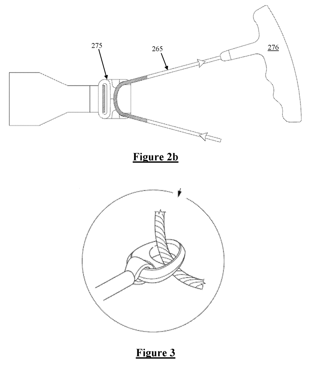
The invention relates to a body stretching device that can help users build tension in their connectors while keeping the load on their arms equal to or less than the load on their back brace. The device includes a pulley system with at least one sheavless block, which helps users easily build tension while keeping their hands and arms in a static stretching position. The sheavless blocks have a friction surface that maximizes static friction to reduce the dynamic friction during connector movement and ease the load on the user's hands and arms. The device also encourages an upright seated stretching position that is important for individuals with limited leg muscle groups and can aid the elderly or disabled in maintaining a proper spinal alignment.

Problems solved by technology

Often tight calves and hamstrings stop an individual from bending over in a biomechanically efficient manner, and, as a result of this tightness, the lower back becomes overloaded resulting in lower back discomfort.
Conversely, if the lower back is inflamed / irritated this can cause neuromuscular related discomfort causing the leg musculature to tighten up; which in turn leads to increased discomfort when the individual tries everyday movements such as walking, sitting up or down, bending over etc.
However, due to the opposed forces applied to the belt applied via the arms of the user the shoulders and upper spine typically roll forward, creating an unwanted bend in the upper spine as well as placing unnecessary stress on the lower back.
Such devices typically do not cater for users of differing height, girth and / or flexibility, and can thus inappropriately pre-tension the user's muscles or misplace the user's limbs prior to use or when finishing use.

Method used


Image

  • A dual hand controlled device for leg stretching and/or activation
  • A dual hand controlled device for leg stretching and/or activation
  • A dual hand controlled device for leg stretching and/or activation

Examples


Embodiment Construction

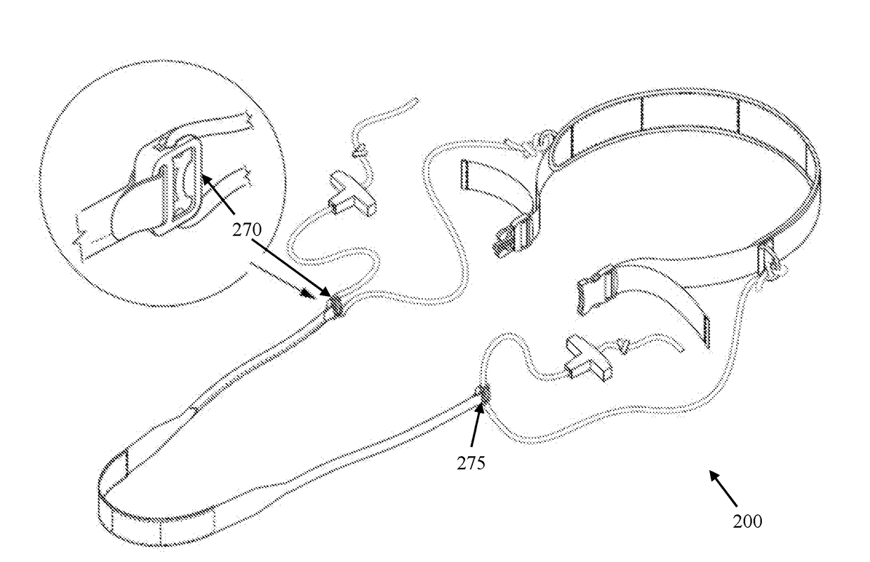
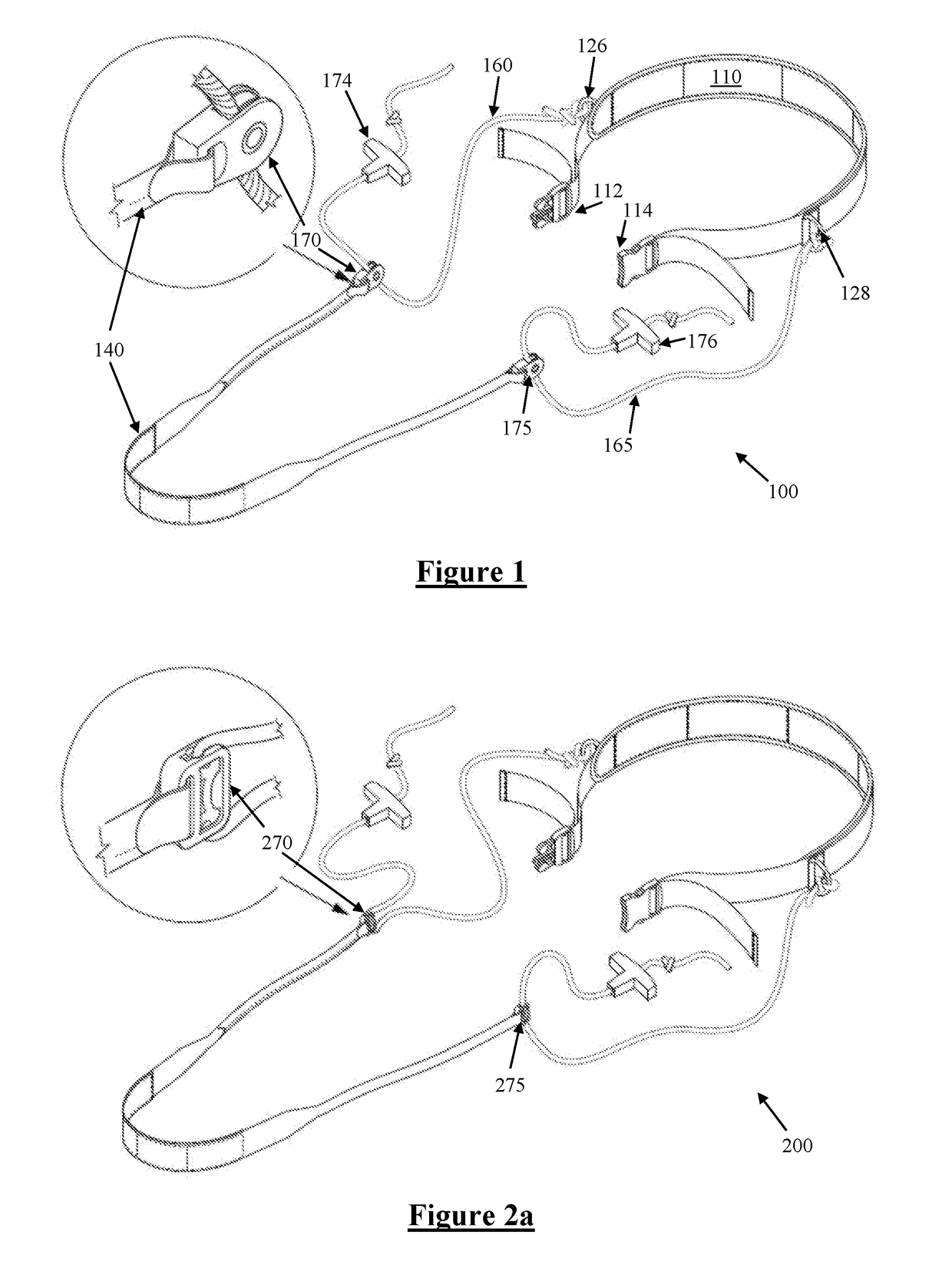
[0043]FIG. 1 illustrates a hand controlled leg stretching device 100 according to a preferred embodiment of the invention. The leg stretching device 100 comprises a lower back brace 110. The lower back brace 110 fits around the lower back / lumbar region and waist of the user such that ends of the lower back brace 110 are fastenable to each other through the use of a side release clip buckle 112, 114. The buckle 112, 114 is adjustable and allows the girth of the lower back brace 110 to be adjusted to snugly hold the waist of the current user.

[0044]The lower back brace 110 has affixed rings 126, 128, positioned such that when the brace 110 is worn by the user each of the rings 126 and 128 is located approximately at the respective hip of the user. The first and second rings 126, 128 are D-shaped metal rings fastened to the lower back brace 110 by stitching.

[0045]Fastened to the first ring 126 is a first end of a first rope 160, and fastened to a second ring 28 is the first end of a sec...


PUM


Abstract

An independent stretching device comprises a back brace configured to pass across and brace against a user's back. A first connector is secured to a first end of the lower back brace, and is threaded through a first pulley. A second connector is secured to a second end of the lower back brace on an opposite side of the user to the first end of the back brace, the second connector being threaded through a second pulley. A foot stirrup is provided for receiving a foot of the user, and has a first end connected to the first pulley and a second end connected to the second pulley. Tension applied to respective distal ends of the first and second connectors distal from the back brace creates tension which urges the foot stirrup and the back brace toward each other.

Description

TECHNICAL FIELD[0001]The present invention relates to a hand controlled leg stretch device for stretching the leg muscles of the user, and in particular provides a dual interdependent, hand controlled leg stretching device that utilises two horizontally opposed pulleys or sheaveless blocks which allows the feet and legs to be substantially aligned with the lower back of the user and avoid or minimise loads associated with unnecessary spinal flexion.BACKGROUND OF THE INVENTION[0002]There is a direct relationship between the lower back and the leg muscle groups. For example the sciatic nerve begins in the lower back and runs through the buttocks and down the lower limbs. The sciatic nerve is the largest nerve in the human body. Sciatica is a set of symptoms not a diagnosis. Therefore in this and other examples it makes sense that when people experience lower back-related symptoms with accompanying discomfort in their lower limbs that the interrelationship between the two areas be cons...

Claims


Application Information

Patent Timeline
Patent Type & Authority Applications(United States)
IPC IPC(8): A61H1/02
CPCA61H1/0237A61H2201/1276A61H2201/1635A61H2201/164A61H2201/1652A61H2203/0425A61H2203/0456A61H2201/0192A61H1/02A61H2201/1269A63B21/154A63B23/03575A63B2208/0238A63B2208/0252A63B21/4009A63B21/4015A63B21/4019A61H15/00
Inventor ANDREWS, STUART
Owner ANDREWS STUART
Learn More