Insulated wire

a technology of insulated wires and wires, applied in the direction of insulated conductors, cables, conductors, etc., can solve the problems of easy unsatisfactory measurement, and inability to achieve automatic transmission or continuously variable transmission, etc., to achieve high-temperature fluid resistance and restrain fatigue of insulated wires

Inactive Publication Date: 2018-10-18
AUTONETWORKS TECH LTD +2
View PDF0 Cites 1 Cited by
  • Summary
  • Abstract
  • Description
  • Claims
  • Application Information

AI Technical Summary

Benefits of technology

[0012]The insulated wire has a specific configuration as described above. According to such a configuration, fatigue of the insulated wire can be restrained even when the insulated wire is reduced in diameter, routed in an automatic transmission or a continuously variable transmission, and shaken by AT fluid or CVT fluid. Further, in the insulated wire, the insulator is hardly damaged by high-temperature AT fluid or high-temperature CVT fluid in the automatic transmission or the continuously variable transmission, and excels in high-temperature fluid resistance. Also, in the insulated wire, an insulation breakdown hardly occurs in a spark test.

Problems solved by technology

An automatic transmission or a continuously variable transmission has no sufficient space therein for routing an insulated wire.
As a result, the insulated wire is bent in the automatic transmission or the continuously variable transmission, so that the fatigue of the insulated wire easily proceeds.
However, such measure is not desirable because it limits the flexibility in routing path and / or routing form.

Method used


Image

  • Insulated wire
  • Insulated wire

Examples


embodiment 1

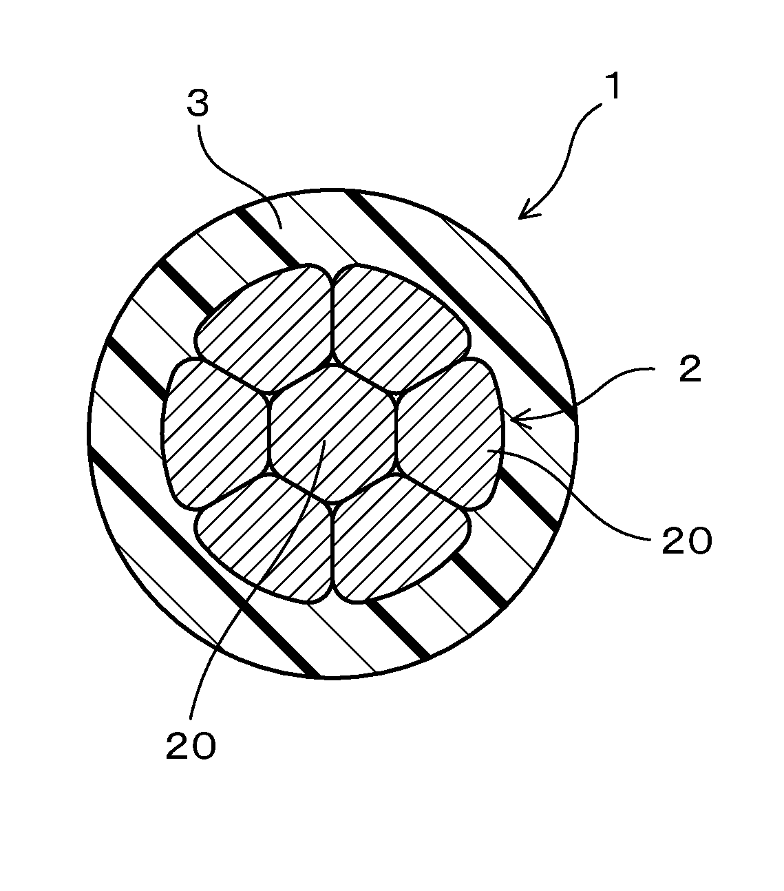
[0032]An insulated wire of Embodiment 1 will be described with reference to FIG. 1. As shown in FIG. 1, an insulated wire 1 of the present embodiment includes a conductor 2 and an insulator 3 that covers an outer circumference of the conductor 2. The cross-sectional area of the conductor 2 is 0.4 mm2 or less. The insulator 3 contains a polymer having S or F in a main chain, and has a thickness of 0.05 mm or more. The density of the insulated wire is 3.1 g / cm3 or more.

[0033]In the present embodiment, the density of the insulator 3 is 1.5 g / cm3 or more. The insulator 3 is composed of a polysulfone resin as a polymer having S in a main chain, or a fluororesin or a fluororubber as a polymer having F in a main chain. The insulated wire 1 is used in a state of being immersed in AT fluid or CVT fluid.

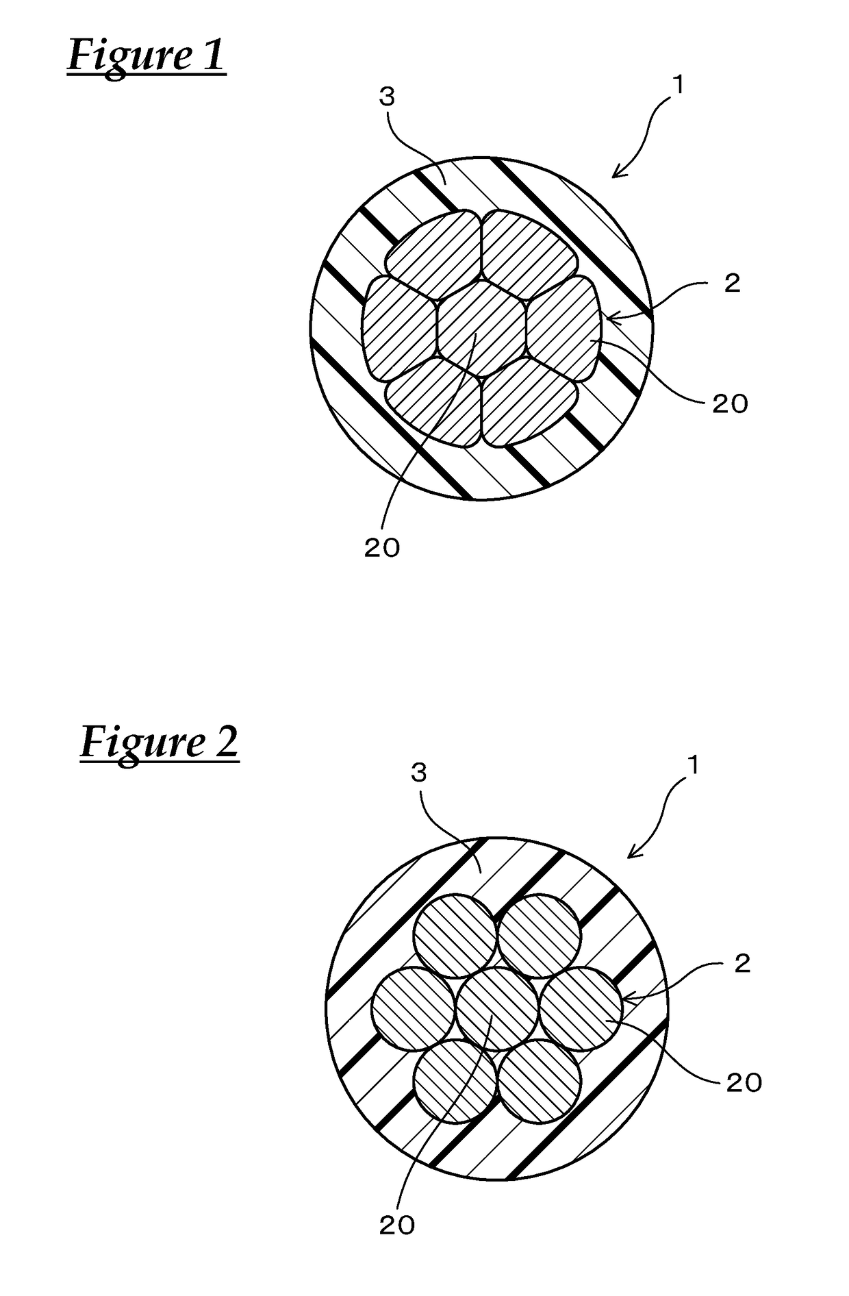
[0034]The conductor 2 is composed of a plurality of metal element wires 20 that are twisted together. In FIG. 1, an example of the insulated wire, in which the conductor 2 has a circular conto...

experimental examples

[0035]Hereinafter, the present configuration will be described more specifically using experimental examples.

[0036]Nine annealed copper wires each having a diameter of 0.15 mm were twisted together, and circularly compressed to prepare a conductor having a cross-section area of 0.16 mm2. In the similar way, nineteen annealed copper wires each having a diameter of 0.13 mm were twisted together to prepare a conductor having a cross-section area of 0.24 mm2. Nineteen annealed copper wires each having a diameter of 0.16 mm were twisted together to prepare a conductor having a cross-section area of 0.38 mm2.

[0037]Each sample insulated wire was prepared by covering the outer circumference of the conductor having an predetermined cross-sectional area shown in Table 1 to be described later with a material for an insulator so as to have a predetermined thickness (a center value) by extrusion covering. In each insulated wire, the weight (g / m), outer diameter (mm) and density (g / cm3) of the in...


PUM

PropertyMeasurementUnit
areaaaaaaaaaaa
thicknessaaaaaaaaaa
densityaaaaaaaaaa

Abstract

An insulated wire in which fatigue of the insulated wire can be restrained even when the insulated wire is disposed in an automatic transmission or a continuously variable transmission, and is shaken by AT fluid or CVT fluid. The insulated wire includes a conductor and an insulator that covers an outer circumference of the conductor. The cross-sectional area of the conductor is 0.4 mm2 or less. The insulator contains a polymer having S or F in a main chain, and has a thickness of 0.05 mm or more. The density of the insulated wire is 3.1 g/cm3 or more. The density of the insulator is preferably 1.5 g/cm3 or more.

Description

CROSS REFERENCE TO RELATED APPLICATIONS[0001]This application claims the priority of Japanese patent application JP2016-071149 filed on Mar. 31, 2016, the entire contents of which are incorporated herein.TECHNICAL FIELD[0002]The present invention relates to an insulated wire.BACKGROUND ART[0003]As a conventional insulated wire to be routed in AT (an automatic transmission) or CVT (a continuously variable transmission), for example, an insulated wire including a conductor and an insulator provided on the outer circumference of the conductor by extrusion covering, in which the conductor has been subjected to Ni plating or Ni alloy plating and the insulator is composed of a resin composition containing at least a sulfonyl group-containing resin having a sulfonyl group in a repeating unit, is publicly known (refer to Patent Document 1 JP-A-2015-141820).SUMMARY[0004]An automatic transmission or a continuously variable transmission has no sufficient space therein for routing an insulated ...

Claims


Application Information

Patent Timeline
Patent Type & Authority Applications(United States)
IPC IPC(8): H01B7/02H01B7/282H01B3/30H01B3/28H01B3/44
CPCH01B7/02H01B7/282H01B3/301H01B3/28H01B3/445Y02A30/14
Inventor MURAO, SATOSHIOOI, HAYATOFURUKAWA, TOYOKIHAYAMI, HIROSHIHORI, KENJI
Owner AUTONETWORKS TECH LTD
Why Eureka
Try Eureka