Variable radius camera mount

Active Publication Date: 2018-10-25
SCHEICH DAVO +1
View PDF8 Cites 0 Cited by
  • Summary
  • Abstract
  • Description
  • Claims
  • Application Information

AI Technical Summary

Benefits of technology

The patent text describes a camera array mount with multiple links that have a stadium shape with a first and second joinder points. The links have set holes and wedges that are aligned to determine the angle between two links. A set pin can be inserted through the set hole to engage the wedge to secure the camera at a specific angle. The technical effect is a versatile and secure mount for cameras that can be adjusted to different angles and directions.

Problems solved by technology

While the aforementioned special effects have become more popular in video and movie production, the traditional set up for obtaining these special effects are complex and cumbersome, such as camera arrays mounted to fixed radius bent pipe or a fixed truss. FIGS. 1A and 1B illustrate an existing metal or aluminum frame or truss structure 10 formed with a fixed radius for supporting the cameras 12 of the array.
The fixed radius bent pipe or truss configuration requires a film or production director to commit to an exact shape to be rigged or set up several days before the shoot, and thus limits the ability of a film crew to make real-time adjustments in their set up as changes in a film shoot may dictate.
Furthermore, the traditional array support structure is hard to transport, especially to remote locations.

Method used


Image

  • Variable radius camera mount
  • Variable radius camera mount
  • Variable radius camera mount

Examples


Embodiment Construction

[0021]The present invention has utility as camera array mounts that are easy to set up, dynamically reconfigurable, compact, and convenient to store and transport. The following description of various embodiments of the invention is not intended to limit the invention to these specific embodiments, but rather to enable any person skilled in the art to make and use this invention through exemplary aspects thereof.

[0022]It is to be understood that in instances where a range of values are provided that the range is intended to encompass not only the end point values of the range but also intermediate values of the range as explicitly being included within the range and varying by the last significant figure of the range. By way of example, a recited range from 1 to 4 is intended to include 1-2, 1-3, 2-4, 3-4, and 1-4.

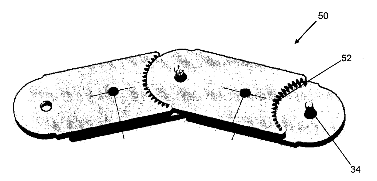
[0023]Embodiments of the inventive links are dynamically configurable into camera array mounts with adjustable radius of curvatures. The inventive links may be made of pla...


PUM


Abstract

A camera array mount made with a series of links is provided that is easy to set up, dynamically reconfigurable, campact, and convenient to store and transport. The links are dynamically configurable into camera array mounts with adjustable radius of curvatures. The links are made of plastic, composites, metals, aluminum, or alloys that can be molded or cast for mass production. The links can be broken down for storage and transport. The links can be adapted for various camera sizes and camera mounts. The links provide improved indexing with angled slots that reduce pin slop. The links provide an optimized weight to support ratio.

Description

CROSS REFERENCE TO RELATED APPLICATIONS[0001]This application claims priority benefit of U.S. Provisional Application Ser. No. 62 / 134,909 filed 18 Mar. 2015; the contents of which are hereby incorporated by reference.FIELD OF THE INVENTION[0002]The present invention generally relates to the field of photography, and more specifically to a new and useful device for constructing dynamic camera arrays.BACKGROUND OF THE INVENTION[0003]A camera array is a formation of multiple cameras that are networked to a controller to capture an image simultaneously or in a synchronized order from each individual camera perspective or angle. When the images or captured frames are edited together many types of photographic and video effects may be obtained. For example, when the cameras in an array are triggered simultaneously and the captured frame images are edited together a moment in time appears frozen as a viewer is moved around the composite image. In addition to the frozen moment additional sp...

Claims


Application Information

Patent Timeline
IPC IPC(8): G03B17/56F16M11/08F16M13/00
CPCG03B17/561F16M2200/024F16M13/00F16M11/08F16M11/10F16M11/04F16M11/12F16M11/18G03B17/56G03B37/04
Inventor SCHEICH, DAVO
Owner SCHEICH DAVO
Why Eureka
Try Eureka