
Controller for a motor vehicle and method

a technology for controlling a motor vehicle and a control box, which is applied in the direction of speed controllers, electric vehicles, road vehicles, etc., can solve the problems of generating an audible noise and/or jerk experienced by the driver or a passenger, and the torque distribution between torque sources also affects the stability of the vehicl

Active Publication Date: 2018-11-01
JAGUAR LAND ROVER LTD
View PDF0 Cites 13 Cited by
  • Summary
  • Abstract
  • Description
  • Claims
  • Application Information

AI Technical Summary

Benefits of technology

The patent is about a method for operating a vehicle with a reduced-tolerance powertrain that helps to prevent excessive noise, vibration, and harshness for the vehicle occupants. This is achieved by controlling the direction of torque application to the vehicle's wheels in the same direction relative to the vehicle body, which prevents lash crossing between the various drive torque sources and the wheels. By using components of reduced tolerance, the method allows for a reduction in costs of the vehicle and also provides better traction for the wheels during acceleration and braking. Additionally, the patent explains how the direction of torque application and weight shifts of the vehicle during acceleration and braking affect the traction of the wheels and how this impact is further improved by controlling the direction of torque application.

Problems solved by technology

When the direction of torque transmission through the device reverses the backlash is crossed and this can result in the generation of an audible noise and / or jerk experienced by the driver or a passenger.
It is recognised that the torque distribution between torque sources also affects stability of the vehicle.

Method used


Image

  • Controller for a motor vehicle and method
  • Controller for a motor vehicle and method
  • Controller for a motor vehicle and method

Examples


Embodiment Construction

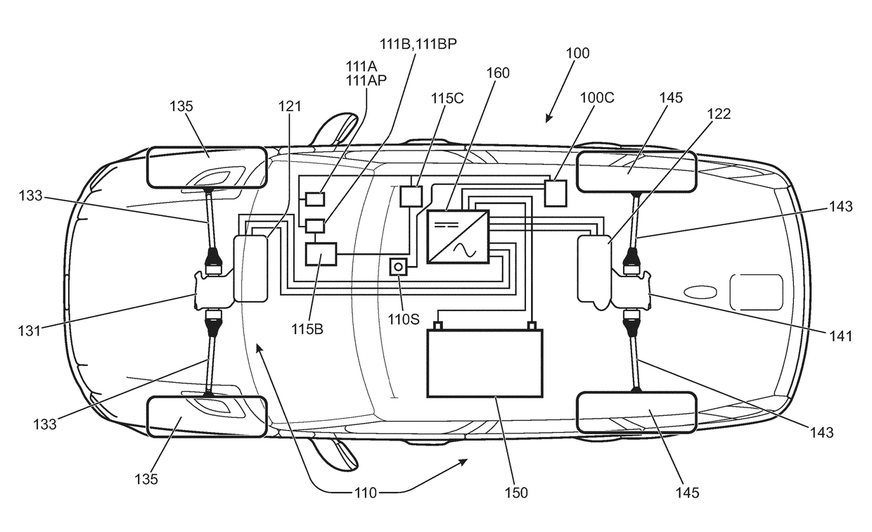
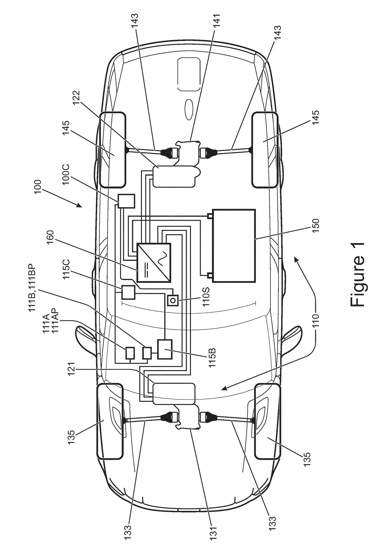
[0038]FIG. 1 is a schematic illustration of a vehicle 100 according to an embodiment of the present invention. The vehicle 100 has a powertrain 110 having first and second electric machines 121, 122 each operable as a propulsion motor (generating positive drive torque in the direction of rotation of the electric machine) or as a generator (generating electrical charge by applying negative drive torque, being drive torque in a direction that is against the actual direction of rotation of the electric machine). The first electric machine 121 is arranged to drive a pair of front wheels 135 of the vehicle via a first torque transfer arrangement of the powertrain 110 that has a front differential gearbox 131 and a pair of front half shafts 133. The second electric machine 122 is arranged to drive a pair of rear wheels 145 of the vehicle via a second torque transfer arrangement of the powertrain 110 that has a rear differential gearbox 141 and a pair of rear half shafts 143. The electric ...


PUM


Abstract

A controller for a motor vehicle powertrain, the controller being configured to control the amount of torque generated by each of a plurality of drive torque sources, each drive torque source being coupled via a respective torque transfer arrangement to a respective group of one or more wheels, the controller being configured to cause a first of the drive torque sources, during acceleration, deceleration and substantially constant speed operation, substantially continually to apply a drive torque to a first group of one or more wheels to which the first drive torque source is coupled acting in a first direction relative to a longitudinal axis of the vehicle and causes a second of the drive torque sources, during acceleration, deceleration and substantially constant speed operation, substantially continually to apply a drive torque to a second group of one or more wheels to which the second drive torque source is coupled, the direction of drive torque applied to the second group being in a second direction opposite the first such that a net drive torque applied to the first and second group in combination corresponds substantially to a predetermined drive torque demand value, the predetermined torque demand value being determined at least in part by reference to a torque demand signal received by the controller.

Description

TECHNICAL FIELD[0001]The present disclosure relates to a controller for a motor vehicle and method. Aspects of the invention relate to a controller and a method.BACKGROUND[0002]It is known to provide an electrically driven vehicle whereby a battery provides electrical power through an inverter to a drive motor. The drive motor is generally connected to two wheels of the vehicle through a torque transfer assembly that has a transmission coupled to a differential gearbox via a drive shaft. The differential gearbox delivers drive torque to side shafts of the assembly that in turn deliver torque to each of two wheels of the vehicle.[0003]It is a characteristic of torque transfer devices such as geared transmissions and differential gearboxes that backlash is present within each gear mesh thereof and also in supporting bearings. When the direction of torque transmission through the device reverses the backlash is crossed and this can result in the generation of an audible noise and / or je...

Claims


Application Information

Patent Timeline
Patent Type & Authority Applications(United States)
IPC IPC(8): B60L15/32B60W10/08B60W20/17
CPCB60L15/32B60W10/08B60W20/17B60L15/10B60L15/2072B60L15/2063B60W2720/406B60L2240/423B60W2710/083B60L15/20Y02T10/72B60W2720/403B60Y2200/91B60K6/52B60W10/06B60W10/26B60W20/13B60W30/18109B60W30/18127B60W20/14B60W30/02Y02T10/62B60W20/15B60L50/00B60K6/22B60W10/119B60W2300/18
Inventor HANCOCK, MATTHEWLIGGINS, STEVEMESSAGE, SIMON
Owner JAGUAR LAND ROVER LTD
Learn More